Full-automatic resistor bending machine and resistor bending method

A bending machine, fully automatic technology, applied in the field of resistance manufacturing, can solve the problems of U-shaped structure pin cutting and bending quality not meeting the requirements, and achieve the effects of saving manpower, precise control, and coordinated actions

Active Publication Date: 2013-12-25
QINGDAO JIERUI IND CONTROL TECH CO LTD
View PDF8 Cites 15 Cited by
  • Summary
  • Abstract
  • Description
  • Claims
  • Application Information

AI Technical Summary

Problems solved by technology

The existing resistance bending machine cannot bend the shape with two bends, and the U-shaped structure pin cutting and bending quality of the existing bending machine do not meet the requirements

Method used


Image

  • Full-automatic resistor bending machine and resistor bending method
  • Full-automatic resistor bending machine and resistor bending method
  • Full-automatic resistor bending machine and resistor bending method

Examples


Embodiment Construction

[0066] Specific embodiments of the present invention will be described in detail below in conjunction with the accompanying drawings.

[0067] First, a brief description of the orientation involved in this specific embodiment is given: when referring to the front, back, left, and right of each structural member, it is defined by the position relative to the user in the use state. In addition, the terms "first", "second", and "third" are used for descriptive purposes only, and should not be construed as indicating or implying relative importance.

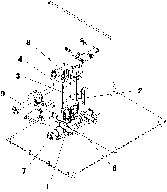
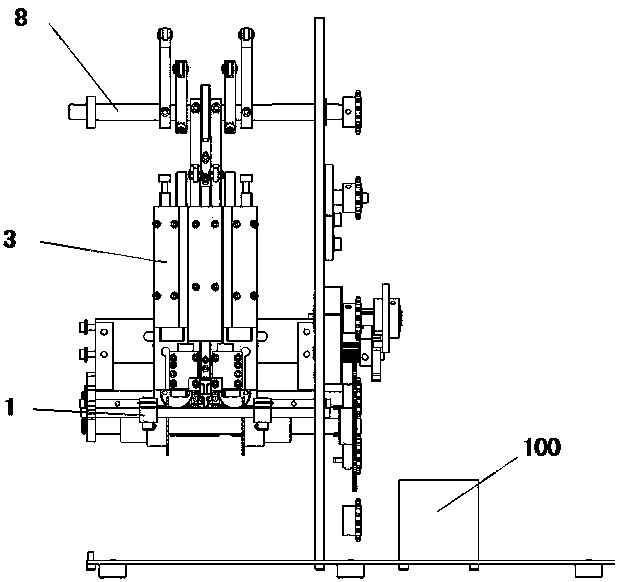
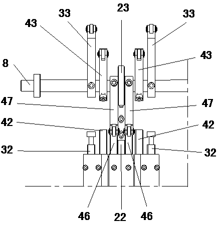
[0068] refer to Figure 1-13 , is an embodiment of the automatic resistance bending machine proposed by the present invention. The automatic resistance bending machine includes a feeding mechanism 1, a tablet pressing mechanism 2, a cutter mechanism 3, a bending mechanism 4, and a motor ( not marked in the figure); the tablet pressing mechanism 2 is arranged above the material preparation table 6, and the cutter mechanism 3 is arran...


PUM


Abstract

The invention discloses a full-automatic resistor bending machine and a resistor bending method. The full-automatic resistor bending machine comprises a feed mechanism, a pressing mechanism, cutter mechanisms, a bending mechanism and a motor. Resistors are conveyed to a preparation table by the feed mechanism; the pressing mechanism is arranged above the preparation table and compresses the resistors on a workbench from the preparation table; the cutter mechanisms are arranged on two sides of the workbench and cut off redundant pins of the resistors; pins of the resistors are bent by the bending mechanism; the feed mechanism, the pressing mechanism, the cutter mechanisms and the bending mechanism are powered by the motor. The full-automatic resistor bending machine and the resistor bending method have the advantages that the pins of the resistors can be automatically and quickly cut off and bent by the full-automatic resistor bending machine, labor is saved, and the production efficiency is improved; the multiple mechanisms are driven to act by the single motor via chains, so that the cost is saved, actions of the various mechanisms are coordinated during production, the production takt can be changed by means of adjusting the rotation speed of the motor, and the production efficiency is improved; action sequences and action moments of the various mechanisms are controlled by the aid of cams, and accordingly can be controlled precisely.

Description

technical field [0001] The invention relates to the technical field of resistance manufacturing, in particular to an automatic resistance bending machine and a resistance bending method. Background technique [0002] After the resistors are produced, they all have two pins. In order to facilitate transportation, storage, etc., the ends of the two pins are respectively fixed in two parallel tapes, and multiple resistors evenly distributed on the tapes form a resistance material. row; then the two pins of the resistor are manufactured into different lengths and shapes according to the needs of different devices. [0003] The processing of the two pins of the resistor was originally done manually. In order to increase work efficiency, a semi-automatic or manual resistance bending machine appeared. The semi-automatic resistance bending machine requires manual loading and frequent start-up, and its production efficiency is low; at the same time, its bending mechanism adopts stam...

Claims


Application Information

Patent Timeline
Patent Type & Authority Applications(China)
IPC IPC(8): B21F1/00B21F11/00
Inventor 赵奎贺保卫秦晓禹王华勇魏立明王绘忠庄绪明张超鄢西华
Owner QINGDAO JIERUI IND CONTROL TECH CO LTD
Why Eureka
Try Eureka