Liquid crystal display device

a liquid crystal display and display device technology, applied in lighting device details, lighting and heating apparatus, instruments, etc., can solve the problems of large changes in luminance and difficulty in forming a micro lens having a flat top, and achieve the effect of wide viewing angle range and high front luminan

Active Publication Date: 2009-03-12
PANASONIC LIQUID CRYSTAL DISPLAY CO LTD +1
View PDF6 Cites 22 Cited by
  • Summary
  • Abstract
  • Description
  • Claims
  • Application Information

AI Technical Summary

Benefits of technology

[0015]The present invention is makes it possible to provide a simply configured liquid crystal display device capable of providing a high fr...

Problems solved by technology

As described above, there arises a problem that the luminance largely changes when the viewing an...

Method used


Image

  • Liquid crystal display device
  • Liquid crystal display device
  • Liquid crystal display device

Examples


Embodiment Construction

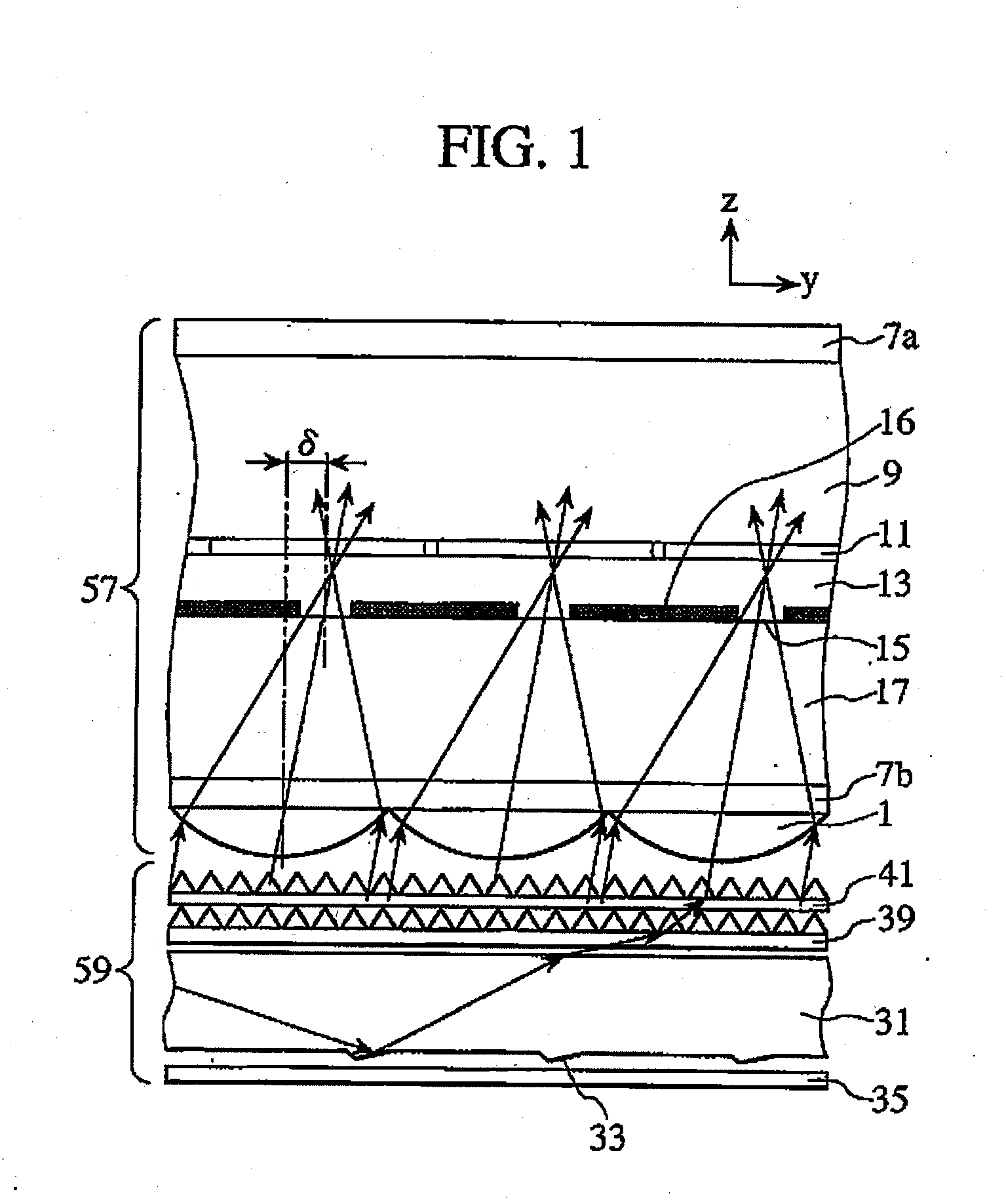
[0033]A first embodiment of the present invention will be explained below with reference to FIGS. 1 to 13.

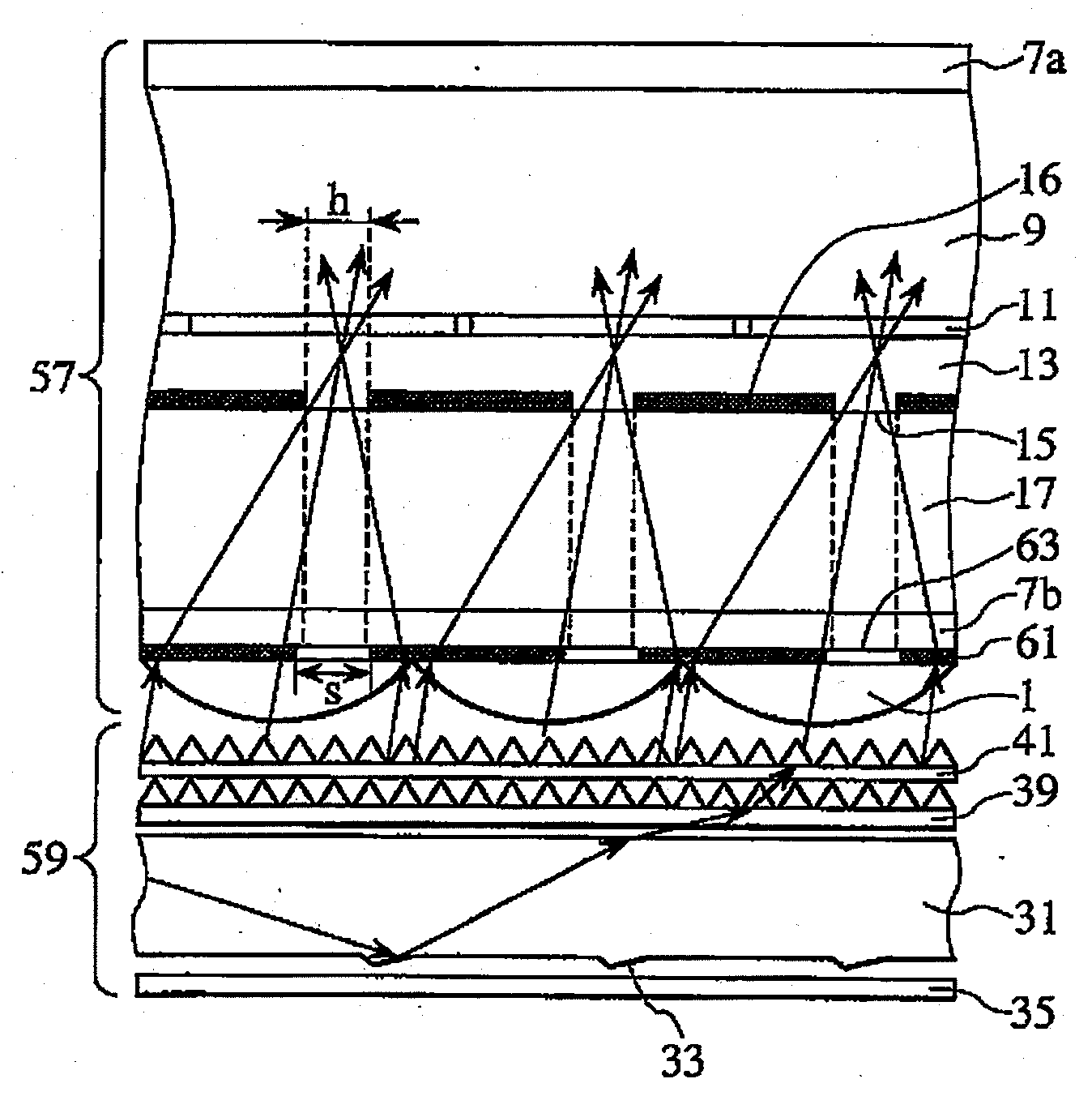
[0034]FIG. 1 is a sectional view showing a planar light-emitting element and a liquid crystal display element included in a liquid crystal display device. Reference numeral 57 denotes a transflective liquid crystal display element having a reflective portion and a transmissive portion within the same pixel, as a liquid crystal display element. Reference numeral 59 denotes a backlight which irradiates the liquid crystal display element 57 with light from a light source, as a planar light-emitting element.

[0035]Light emitted from a light source (disposed on the left-hand side of FIG. 1, not shown) repeatedly reflects and propagates within a light guide plate 31 which is a light guide element. The light guide plate 31 is formed with a reflecting groove 33 below the plate 31, i.e., on the side opposite to the liquid crystal display element 57 (on the side opposite to the light extra...


PUM


Abstract

An object of the present invention is to provide a simply configured liquid crystal display device capable of providing a high front luminance when light obliquely enters a micro lens array. The liquid crystal display device comprises: a pair of polarizing plates which sandwich a pair of substrates; a liquid crystal layer sandwiched by the pair of substrates; transmission openings formed in a pixel to limit the quantity of light which penetrates the liquid crystal layer; condensing elements formed on the side of one of the substrates, opposite to the side on which the liquid crystal layer is disposed, to condense light to the transmission openings; and a planar light-emitting element which emits light to be applied to the condensing elements; wherein the light to be emitted from the planar light-emitting element forms a certain angle with respect to its perpendicular when emitted; and wherein the position of the transmission opening is relatively shifted with respect to that of the condensing element so as to increase the quantity of light which penetrates the transmission opening, in association with the light-emitting direction of the planar light-emitting element.

Description

BACKGROUND OF THE INVENTION[0001]1. Field of the Invention[0002]The present invention relates to a liquid crystal display device which uses a transmissive or transflective liquid crystal layer.[0003]2. Description of the Related Art[0004]JP-A-2005-275142 discloses a display panel which includes a micro lens array composed of a plurality of micro lenses, each having a flat top, disposed on the backlight side of a liquid crystal display panel in order to expand the viewing angle without reducing the front luminance.[0005]Japanese patent No. 3931989 discloses a display device adapted to improve the efficiency of utilization of light from the illumination device to increase the luminance. This display device includes an illumination device, a display panel having a plurality of pixels, and condensing elements disposed between the illumination device and the display panel. The condensing elements are disposed in association with a transmissive region of the pixels and a converging point ...

Claims


Application Information

Patent Timeline
IPC IPC(8): G02F1/13357G02F1/1335
CPCG02B6/0038G02B6/0053G02F1/133504G02F2001/133567G02F1/133526G02F1/133555G02F1/133615G02F1/133512G02F1/133567
Inventor SUGITA, TATSUYAKOMURA, SHINICHINAGATA, TETSUYAADACHI, MASAYA
Owner PANASONIC LIQUID CRYSTAL DISPLAY CO LTD
Why Eureka
Try Eureka