Blue phosphor, light-emitting device, and plasma display panel

a light-emitting device and blue phosphor technology, applied in the direction of discharge tube luminescent screen, discharge tube/lamp details, luminescent composition, etc., can solve the problems of significant luminance degradation, phosphors cannot inhibit the degradation of luminance during driving, and significant luminance degradation, etc., to achieve low luminance degradation and high luminance

Inactive Publication Date: 2012-08-07
PANASONIC CORP
View PDF10 Cites 0 Cited by
  • Summary
  • Abstract
  • Description
  • Claims
  • Application Information

AI Technical Summary

Benefits of technology

[0007]The present invention has achieved a solution to the above conventional problems, and it is an object of the present invention to provide a phosphor having high luminance, a property of low luminance degradation during driving of a light-emitting device and manufacturing processes, and chromaticity y in PDP comparable to that of BAM:Eu. It is a further object of the present invention to provide a long-life light-emitting device, particularly PDP, using the above phosphor.
[0018]According to the present invention, a phosphor that has good luminance and chromaticity and shows less luminance degradation during driving and manufacturing processes is provided. A long-life light-emitting device such as a PDP that has good luminance and chromaticity and shows less luminance degradation during the long-time driving is provided.

Problems solved by technology

However, when a light-emitting device using the blue phosphor BAM:Eu is driven for a long period, the luminance is degraded significantly.
According to elaborate studies of the present inventors, however, it has been found that in most cases in the light-emitting devices using the above conventional phosphors, the phosphors can not inhibit the degradation of luminance during driving while maintaining the high luminance.
Furthermore, when the above conventional phosphor having a Sr site is used, the degradation of luminance is significant during the manufacturing processes of applying and firing the phosphor with an organic binder.
These constitute problems.

Method used


Image

  • Blue phosphor, light-emitting device, and plasma display panel
  • Blue phosphor, light-emitting device, and plasma display panel
  • Blue phosphor, light-emitting device, and plasma display panel

Examples


Embodiment Construction

[0023]Hereinafter, embodiments of the present invention will be described in detail.

[0024]The blue phosphor of the present invention is represented by the general formula xSrO.yEuO.MgO.zSiO2 (where 2.970≦x≦3.500, 0.001≦y≦0.030, 1.900≦z≦2.100). With respect to x, y and z, preferable ranges are 2.982≦x≦2.999, 0.001≦y≦0.018, and 1.980≦z≦2.020, respectively. z is preferably 2.00.

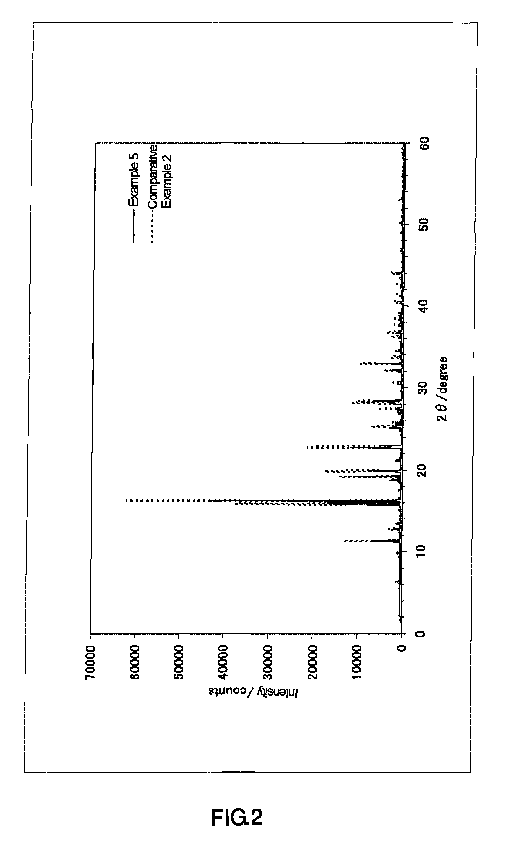
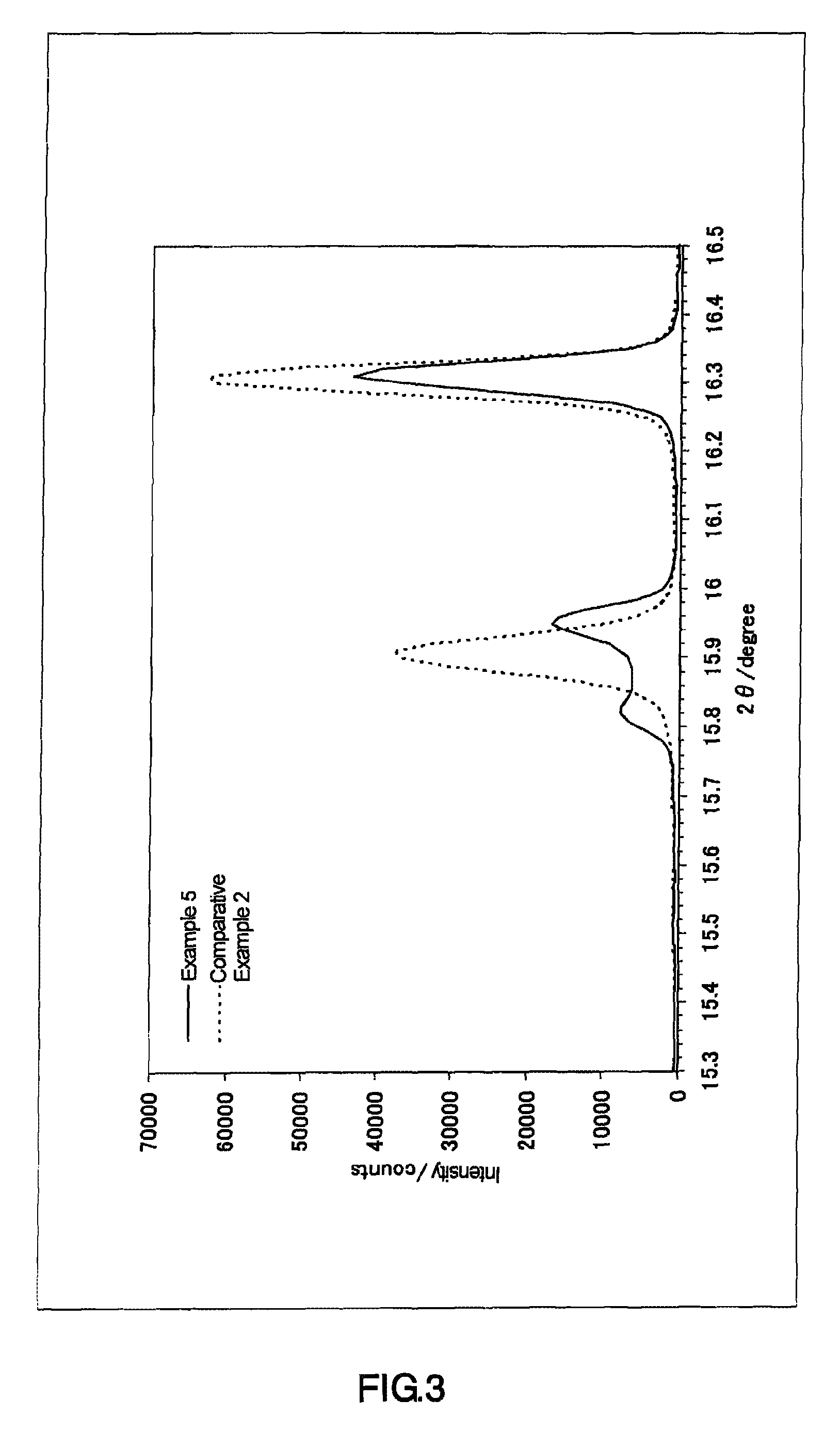
[0025]The blue phosphor of the present invention is characterized in that a main peak is present in the range of diffraction angle 2θ=16.1 to 16.5 degree in the X-ray diffraction pattern obtained by measurement on the blue phosphor using an X-ray with a wavelength of 0.774 Å, and at least two peaks whose tops are located in the certain range of diffraction angle 2θ are present (condition A). Alternatively, a main peak is present in the range of diffraction angle 2θ=16.1 to 16.5 degree, as well as a peak or a group of peaks consisting of overlapping peaks whose top is or tops are located in the certain range of d...


PUM

PropertyMeasurementUnit
diffraction angle 2θaaaaaaaaaa

Abstract

The present invention provides a phosphor having high luminance, a property of low luminance degradation during driving of a light-emitting device and manufacturing processes, and chromaticity y in PDP comparable to that of BAM:Eu. The present invention is the phosphor represented by the general formula xSrO.yEuO.MgO.zSiO2 where 2.970≦x≦3.500, 0.001 ≦y≦0.030, and 1.900≦z≦2.100 are satisfied, wherein a main peak is present in the range of diffraction angle 2θ=16.1 to 16.5 degree in the X-ray diffraction pattern obtained by measurement on the blue phosphor using an X-ray with a wavelength of 0.774 Å, and at least one condition of the following conditions (A1) and (A2) is satisfied: (A1) at least two peaks whose tops are located in the range of diffraction angle 2θ=15.3 to 16.1 degree are present; and (A2) at least two peaks whose tops are located in the range of diffraction angle 2θ=22.2 to 23.3 degree are present.

Description

TECHNICAL FIELD[0001]The present invention relates to a blue phosphor, and a light-emitting device such as a plasma display panel (hereinafter referred to as PDP).BACKGROUND ART[0002]Various aluminate phosphors have been put to practical use as phosphors for energy-saving fluorescent lamps. As a blue phosphor, for example, (Ba,Sr)MgAl10O17:Eu (BAM:Eu) is mentioned. As a green phosphor, for example, CeMgAl11O19:Tb, BaMgAl10O17:Eu,Mn, and the like are mentioned.[0003]In recent years, BAM:Eu, which has high luminance under vacuum-ultraviolet excitation, has been used as a blue phosphor for a PDP.[0004]However, when a light-emitting device using the blue phosphor BAM:Eu is driven for a long period, the luminance is degraded significantly. Hence, in the light-emitting device use, particularly in the PDP use, there is a strong demand for a phosphor that shows less luminance degradation even after the long-time driving.[0005]On the other hand, methods using certain types of silicate phosph...

Claims


Application Information

Patent Timeline
Patent Type & Authority Patents(United States)
IPC IPC(8): C09K11/08C09K11/77C09K11/02C09K11/66H01J17/49
CPCC09K11/7734H01J11/12H01J11/42C09K11/77342C09K11/77
Inventor KITAMURA, YAYOISHIRAISHI, SEIGOOKUYAMA, KOJIROSAKAI, MASAHIRO
Owner PANASONIC CORP
Why Eureka
Try Eureka