Multi-level inverter

a multi-level inverter and inverter technology, applied in the direction of power conversion systems, ac-ac conversion, electrical apparatus, etc., can solve the problems of inability to perform all operations of the inverter, damage to the unit cell, and increase the voltage of the dc-link

Active Publication Date: 2017-11-21
LSIS CO LTD
View PDF27 Cites 25 Cited by
  • Summary
  • Abstract
  • Description
  • Claims
  • Application Information

AI Technical Summary

Benefits of technology

[0011]In accordance with one aspect of some embodiments, a multi-level inverter includes a first capacitor and a second capacitor coupled in series to each other, a plurality switches for generating a multi-level output voltage by using a voltage charged in the first capacitor and the second capacitor and a plurality of diodes respectively coupled in parallel to the plurality of switches, a first output terminal and a second output terminal for outputting the output voltage, and a controller for switching a state of each of the plurality of switches to an on or off state according to one of predetermined bypass modes, thereby interrupting the output of the output voltage through the first output terminal and the second output terminal.

Problems solved by technology

However, in an inverter having no bypass switch for controlling a bypass operation for each unit cell, a DC-link voltage increases due to rectification of an inverse-parallel diode of a power switch used in an abnormal unit cell.
As a result, unit cells are damaged, and all operations of the inverter cannot be performed.

Method used


Image

  • Multi-level inverter
  • Multi-level inverter
  • Multi-level inverter

Examples


Embodiment Construction

[0020]Hereinafter, disclosed embodiments will be described in detail with reference to the accompanying drawings. It should be understood that the present disclosure is not limited to the following embodiments, and that the embodiments are provided for illustrative purposes only. The scope of the disclosure should be defined only by the accompanying claims and equivalents thereof. In the drawings, like reference numerals designate identical or corresponding parts throughout the several views.

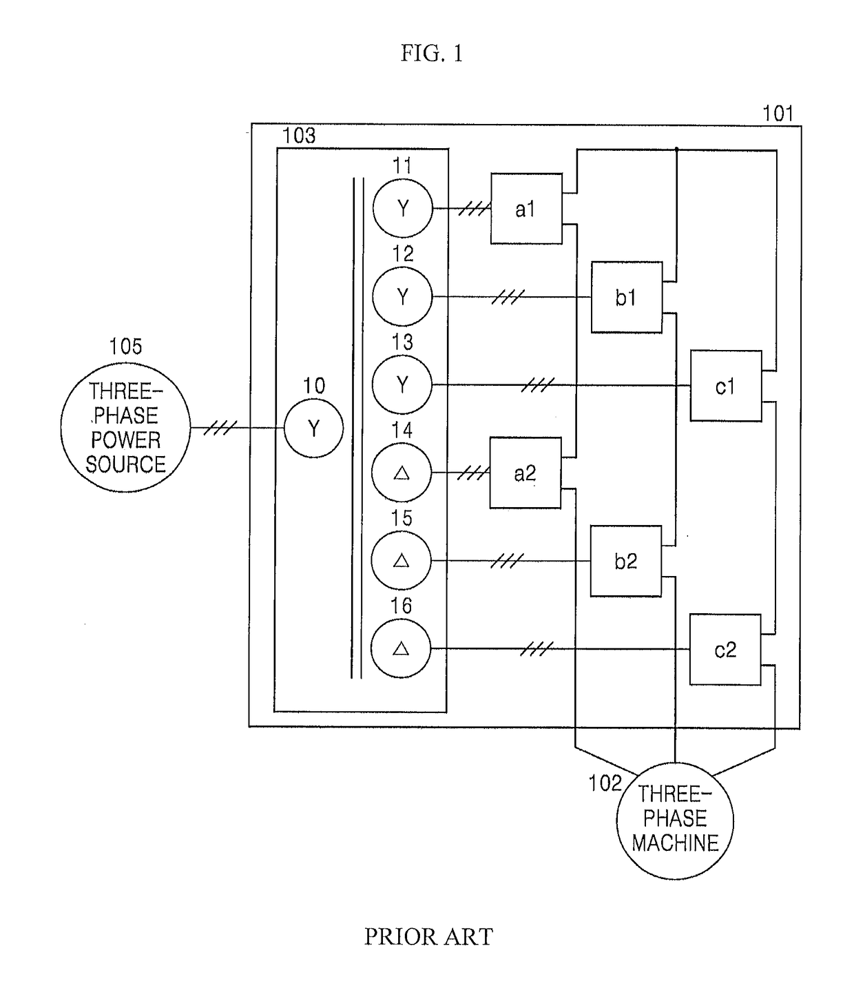
[0021]FIG. 1 is a configuration diagram of a cascaded multi-level inverter.

[0022]The cascaded multi-level inverter 101 shown in FIG. 1 is configured with unit cells a1, b1, c1, a2, b2, and c2 in two stages, but the number of unit cells may vary depending on system requirements. Each of the unit cells a1, b1, c1, a2, b2, and c2 has an independent single-phase inverter structure. As shown in FIG. 1, the unit cells a1, b1, c1, a2, b2, and c2 are coupled in series, thereby obtaining a high voltage.

[...


PUM


Abstract

The present disclosure relates to a multi-level inverter capable of performing a bypass operation without adding any separate module. The multi-level inverter includes a first capacitor and a second capacitor coupled in series to each other, a plurality switches for generating a multi-level output voltage by using a voltage charged in the first capacitor and the second capacitor and a plurality of diodes respectively coupled in parallel to the plurality of switches, a first output terminal and a second output terminal for outputting the output voltage, and a controller for switching a state of each of the plurality of switches to an on or off state according to one of predetermined bypass modes, thereby interrupting the output of the output voltage through the first output terminal and the second output terminal.

Description

CROSS REFERENCE TO RELATED APPLICATION[0001]This application claims the benefit of Korean Patent Application No. 10-2015-0050143, filed on Apr. 9, 2015, which is hereby incorporated by reference in its entirety.BACKGROUND[0002]1. Technical Field[0003]The present disclosure relates to a multi-level inverter, and more particularly, to a multi-level inverter capable of performing a bypass operation without adding any separate module.[0004]2. Description of the Related Art[0005]A medium voltage inverter is an inverter having an input power whose root mean square (RMS) value is over 600V for a line-to-line voltage. The rating power capacity of the medium voltage inverter ranges from a few hundreds of kilowatts to a few tens of megawatts. Various medium voltage inverters are widely used in application fields including fans, pumps, and compressors. Among these medium voltage inverters, a cascaded multi-level inverter is frequently used, which generates an output phase voltage having three ...

Claims


Application Information

Patent Timeline
Patent Type & Authority Patents(United States)
IPC IPC(8): H02M7/483H02M7/487H02M7/49H02M1/32H02M5/458
CPCH02M5/458H02M1/32H02M7/49H02M7/487H02M2001/325H02M7/4835H02M1/325
Inventor CHOI, SEUNG-CHEOLYOO, AN-NO
Owner LSIS CO LTD
Why Eureka
Try Eureka