
Driving assist device

a technology of assist device and assist device, which is applied in the direction of automatic control system, process and machine control, instruments, etc., can solve the problems of proposed failure to take this possibility into consideration, and difficult to ensure safe driving, so as to achieve the effect of ensuring safe driving

Active Publication Date: 2018-01-02
DENSO CORP
View PDF13 Cites 4 Cited by
  • Summary
  • Abstract
  • Description
  • Claims
  • Application Information

AI Technical Summary

Benefits of technology

[0011]It is generally considered that a vehicle driver tends to enter an inattentive state during automated driving. In that regard, compared with manual driving, automated driving tends to be performed following traffic regulations in any situation. Therefore, automated driving continued for a long period of time can cause the driver to feel stress. There are cases in which, as a result of growing of such stress, the driver wanting to be released from the stress tries to switch at least one of the driving operations in the automated driving state to the manual driving state by operating the manual operation unit during automated driving. Because the driver in the situation like this may be in a kind of excited state, it is detected whether the driver is in the excited state. When the driver is found excited, the driver is alerted. In this way, even when the driver enters a dangerous state peculiar to automated driving, the driver can be calmed down, and thereby, safe driving can be ensured.

Problems solved by technology

According to studies by the inventor of this application, however, no matter what maximum tolerable degree of driver's inattentiveness is set, it is difficult to ensure safe driving for the following reasons.
During the automated driving of the vehicle, however, there is possibility that the driver of the vehicle enters a driver state in which ensuring safe driving is difficult and which is supposed not to occur during manual driving.
All in the technologies so far proposed fail to take this possibility into consideration.
When the driver enters such a dangerous state unique to automated driving, it is difficult to ensure safe driving.

Method used


Image

  • Driving assist device
  • Driving assist device
  • Driving assist device

Examples


Embodiment Construction

[0020]An embodiment of the present disclosure will be described below.

[0021]A. Device Configuration

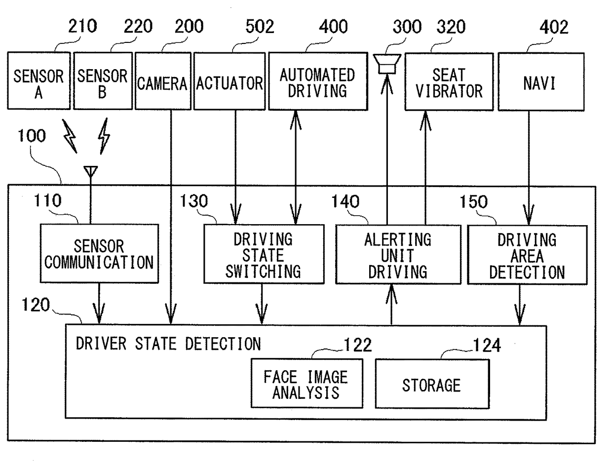
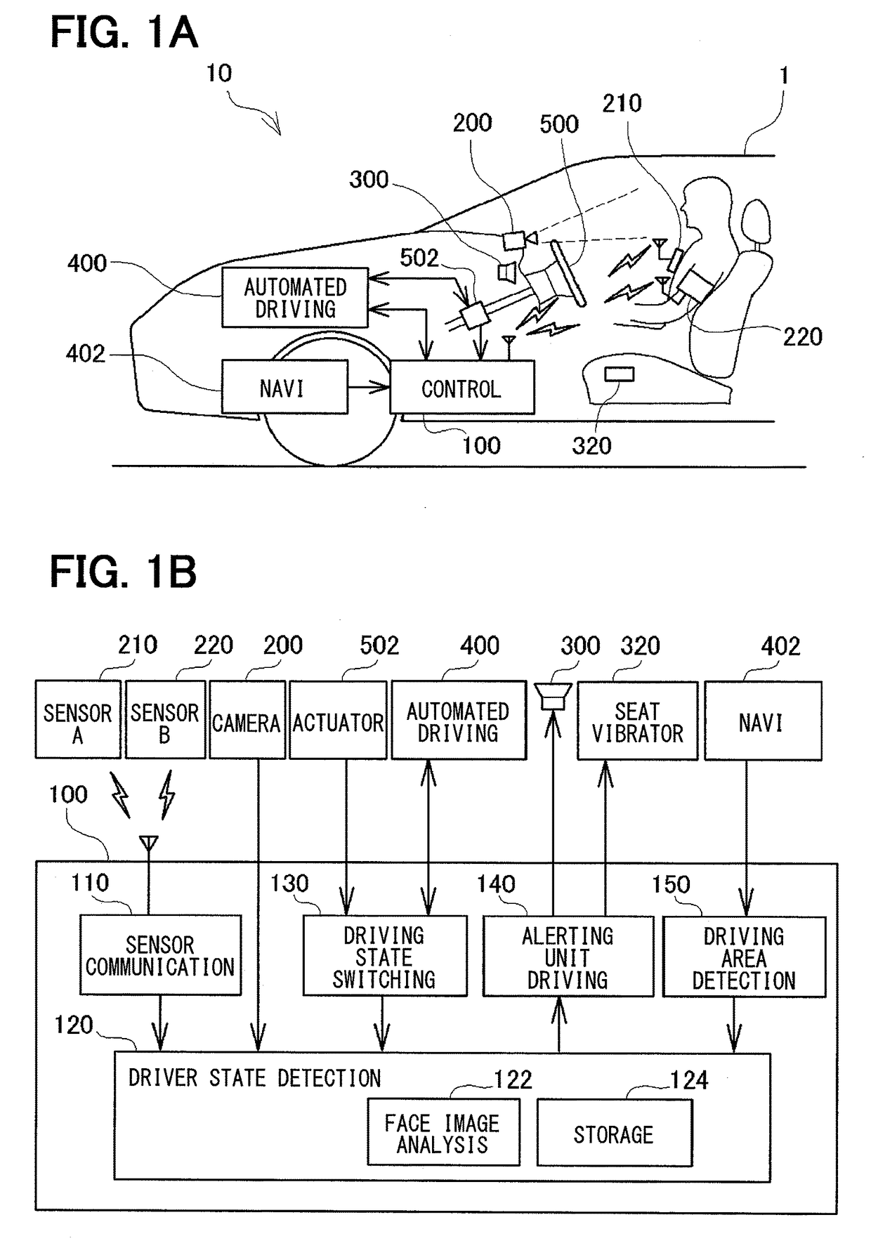
[0022]FIG. 1A shows a vehicle 1 mounted with a driving assist device 10 of the present embodiment. As shown in FIG. 1A, the vehicle 1 is mounted with a control device 100 constituting a main part of the driving assist device 10 of the present embodiment, an automated driving device 400 for automatically driving the vehicle 1, and a car navigation system.

[0023]During manual driving, a driver drives the vehicle 1, for example, by steering a steering wheel 500 and operating an accelerator pedal and a brake pedal (not shown). After the driving state switches to automated driving, the automated driving device 400 operates, on behalf of the driver, the steering wheel 500, the accelerator pedal and the brake pedal. The steering wheel 500 has a shaft attached with an actuator 502 which has a built-in steering angle sensor. The automated driving device 400 operates the steering wheel 500 by dri...


PUM


Abstract

A driving assist device includes a driver state detection unit for detecting an inattentive state as a driver state, an alerting unit for altering the driver upon detection of the inattentive state of the driver, a driving operation unit for being operated by the driver for driving operations; and a driving state switching unit that switches at least one of the driving operations in an automated driving state to a manual driving state when the driver's operation of the driving operation unit is detected during the automated driving state of the vehicle. When at least one of the driving operations in the automated driving state is switched to the manual driving state by the driving state switching unit, the driver state detection unit detects whether the state of the driver is an excited state. When the excited state of the driver is detected, the alerting unit alerts the driver.

Description

CROSS REFERENCE TO RELATED APPLICATIONS[0001]This application is based on Japanese Patent Application No. 2014-24949 filed on Feb. 12, 2014, the disclosure of which is incorporated herein by reference.TECHNICAL FIELD[0002]The present disclosure relates to a driving assist technology applied to a vehicle that is switchable between an automated driving state and a manual driving state. The technology assists a driver in driving the vehicle through detecting a state of the driver.BACKGROUND ART[0003]Technologies have been developed and put to practical use which ensure safe driving of a vehicle through detecting a state of the driver of the vehicle based on, for example, the direction of driver's line of sight and biological information about the driver (e.g. eyelid behavior and heart rate) and, when the driver is found inattentive, alerting the driver. Moreover, in recent years, vehicles have been introduced which automatically perform some of the driving operations (e.g. traveling, t...

Claims


Application Information

Patent Timeline
Patent Type & Authority Patents(United States)
IPC IPC(8): B60W50/00G08B25/08G08B21/06G08B21/02G08G1/16B60W40/08B60W50/14B60W30/12B60W30/16G05D1/00G06N5/04
CPCB60W50/0098B60W30/16B60W40/08B60W50/14G05D1/0088G06N5/04G08B21/02G08B21/06G08B25/08G08G1/16B60W30/12B60W2600/00B60W2050/0071B60W2400/00B60W2540/26B60W2540/22B60W2540/221B60W2556/00B60W60/0059B60W2540/225B60W60/0055B60W2540/229
Inventor OMI, TAKUHIRO
Owner DENSO CORP
Learn More