Sliding door

a sliding door and door body technology, applied in the field of sliding doors, can solve the problems of long life and functionality, and achieve the effect of avoiding the noise produced by the friction between not exposing the tip of the pin

Active Publication Date: 2018-01-16
ELFA INTERNATIONAL
View PDF34 Cites 1 Cited by
  • Summary
  • Abstract
  • Description
  • Claims
  • Application Information

AI Technical Summary

Benefits of technology

[0005]One object of the present disclosure is to improve a sliding door of the initially mention kind. More specifically, a sliding door of the initially mentioned kind has a transmission mechanism which interconnects the wheel holder and the pin such that a movement of the wheel, towards the extended position of the wheel, urges the pin towards its extended position. This makes it possible to approximately maintain a desired distance between the tip of the pin and the rail regardless of how the door is adjusted. Still, it is not necessary to urge the pin against the rail by means of a spring or the like. This has advantages, such as not exposing the tip of the pin to excessive wear against the rail, and avoiding any noise produced by the friction between the tip of the pin and the rail.
[0007]The transmission mechanism may be arranged to maintain a gap between the tip of the pin and the rail. This ensures reliable operation by presenting the tip of the pin to the attenuation and retraction device in a consistent manner. The maintained gap may, as an example, be in the range 2±0.5 mm.
[0010]The pin may comprise a tip, which is intended to interact with the attenuation and retraction device, a wing portion, and a waist portion, on the other side of the wing portion as seen from the tip. The waist portion is narrower than the wing portion, such that the wing portion can be caught by the attenuation and retraction device to pull the pin further from its retracted position. This allows the pin to interact more reliably with an attenuation and retraction device having a catching function.
[0011]The wheel holder and the pin may be mounted together in a cassette. This allows the functionality to be provided as a single component that may be used in different types of doors.

Problems solved by technology

One problem associated with a door of this kind, is how to improve the smooth operation of the door, and have a functionality with a long length of life, while retaining a reliable attenuation and retraction functionality.

Method used


Image

  • Sliding door
  • Sliding door
  • Sliding door

Examples


Embodiment Construction

[0030]The principles of the present invention and their advantages are best understood by referring to the illustrated embodiment depicted in FIGS. 1-14 of the drawings, in which like numbers designate like parts.

[0031]The present disclosure relates generally to a sliding door arrangement. Such an arrangement is typically used to delimit a niche or recess, which may be provided with shelves and may be used as a closet. Another use for a sliding door arrangement is as a room dividing device providing a semi-removable wall. Needless to say, there are other uses.

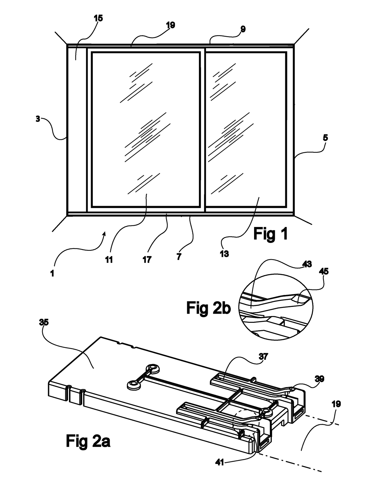
[0032]FIG. 1 illustrates schematically a sliding door arrangement 1. Typically, the door arrangement may be used at the end of a room, extending between a first wall 3 and a second wall 5, and between the floor 7 and the ceiling 9. In the illustrated case, only two doors 11, 13 are used, although the number of doors may even exceed five in some applications. The space 15 behind the doors may be provided with shelves and may be ...


PUM


Abstract

A sliding door for use with a rail system, having a rail, which guides a sliding motion of the door, and an attenuation and retraction device, which brakes the sliding motion of the door at a brake position in the vicinity of a door end position and retracts the door to the end position. The sliding door includes a pin, which is slideably attached to the door, slideable between a pin retracted position and a pin extended position, a tip of the pin interacting with the attenuation and retraction device. The door further includes a wheel carried by a wheel holder, which is arranged to move the wheel between a wheel retracted position and a wheel extended position. A transmission mechanism interconnects the wheel holder and the pin such that a movement of the wheel, towards the wheel extended position, urges the pin towards the pin extended position.

Description

CROSS-REFERENCE TO RELATED APPLICATION[0001]The present application is a nationalization under 35 U.S.C. §371 of International Application No. PCT / EP2014 / 056893 filed under the PCT, having an international filing date of Apr. 7, 2014, which claims priority to European Patent Application No. EP 13163927.0, having a filing date of Apr. 16, 2013.FIELD OF INVENTION[0002]The present disclosure relates to a sliding door, intended for use with a rail system having a rail, which guides a sliding motion of the door, and an attenuation and retraction device, which brakes the sliding motion of the door at a brake position in the vicinity of a door end position and retracts the door to the end position. The sliding door has a pin, which is slideably attached to the door, slideable between a retracted position and an extended position. A tip of the pin is devised to interact with the attenuation and retraction device. The door further has a wheel carried by a wheel holder, which is arranged to m...

Claims


Application Information

Patent Timeline
Patent Type & Authority Patents(United States)
IPC IPC(8): E05F11/00E05D15/06E05F5/00E05F1/16E06B3/46E05F5/02
CPCE05D15/0643E05D15/0626E05D15/0678E05F1/16E06B3/4636E05F5/003E05Y2800/24E05F5/027E05Y2201/412
Inventor NILSSON, PETER
Owner ELFA INTERNATIONAL
Why Eureka
Try Eureka