Effective biasing active circulator with RF choke concept

a technology of active circulators and chokes, applied in electrical equipment, phase shifting networks, one-way transmission networks, etc., can solve the problems of biasing active devices with dc power consumption, and achieve the effect of inhibiting dc power consumption through resistors

Active Publication Date: 2018-02-13
HRL LAB
View PDF10 Cites 1 Cited by
  • Summary
  • Abstract
  • Description
  • Claims
  • Application Information

AI Technical Summary

Benefits of technology

[0014]In still yet another aspect the present invention provides an apparatus for biasing FET transistors in an active circulator comprising means separating a DC bias circuit path and an RF signal path between said FET transistors sufficiently to provide a maximum RF voltage swing across the drains and sources of said FET transistors without providing any resistors in said RF signal path between said FET transistors thereby inhibiting resistive power consumption.

Problems solved by technology

DC power consumption will occur in biasing the active devices (the transistors) and cannot be entirely avoided, but the AC signals need to travel on pathways which avoid DC power consuming resistors used to bias the active devices (the transistors).

Method used


Image

  • Effective biasing active circulator with RF choke concept
  • Effective biasing active circulator with RF choke concept
  • Effective biasing active circulator with RF choke concept

Examples


Embodiment Construction

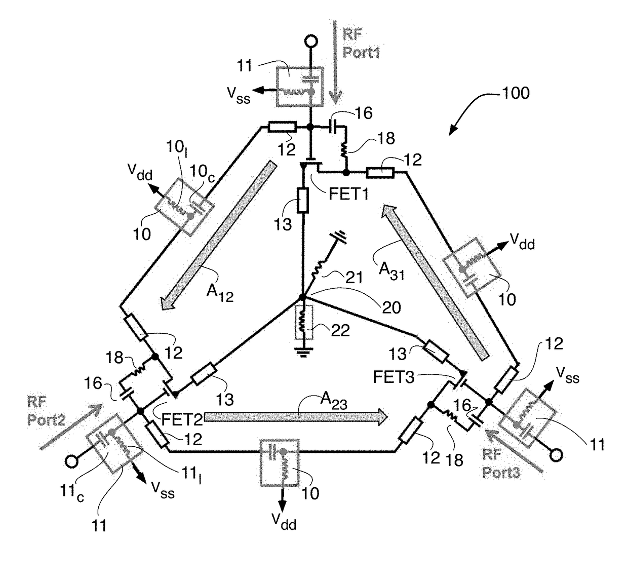
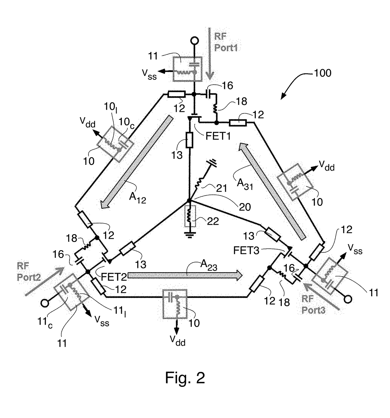
[0024]FIG. 2 depicts a schematic diagram of the new active circulator 100. Basically active circulator consists of three (or more) transistors (FET1, FET2 and FET3) arranged in a ring, with RC feedback and common ground resistors. The gate bias (to Vss) of the each of the three transistors FET1, FET2 and FET3 is provided through one of three choke inductors 11l (inside each of three RF chokes 11), while the drain bias (to Vdd) of the each of the three transistors FET1, FET2 and FET3 is provided through one of three choke inductors 101 (inside each of three RF chokes 10). The three transistors FET1, FET2 and FET3 are depicted (according to the symbol used) as being HEMT devices, but the three transistors FET1, FET2 and FET3 can be implemented as other types of transistors including Bipolar Junction Transistors, CMOS Field Effect Transistors, and Laterally Diffused Metal Oxide Semiconductor Transistors, to name a few. So the use of nomenclature “FET” with respect to transistors FET1, ...


PUM


Abstract

A multi-port active circulator where each of a plurality of FET transistors has (i) a gate connected to an associated port of the multi-port active circulator via a capacitor of an associated one of a plurality of first RF chokes, each of the first RF chokes being connected to a gate of an associated FET transistor of said plurality of transistors, the associated port of said associated FET transistor and to a power supply bias connection; (ii) a source connected to a common point; and (iii) a drain connected to the gate of the same FET transistor by a feedback circuit and connected to the gate of a neighboring FET transistor via a capacitor of one of a plurality of second RF chokes, each of which coupling gates and drains of neighboring FET transistors via capacitors thereof and being connected to another power supply bias connection.

Description

STATEMENT REGARDING FEDERALLY SPONSORED RESEARCH OR DEVELOPMENT[0001]This invention was made under US Government Contact No N00014-11-C-0025 and therefore the US Government may have certain rights in this invention.CROSS REFERENCE TO RELATED APPLICATIONS[0002]None.TECHNICAL FIELD[0003]This invention relates to active circulators.BACKGROUND[0004]Circulators are well known in the prior art. A circulator is an active or passive three- or four-port device, in which a microwave or radio frequency signal entering any port is transmitted only to the next port in rotation.[0005]FIG. 1 shows a prior art three port active circulator. The port numbers are labeled and as can be seen the direction of rotation (referred to in the immediately preceding paragraph) is counter clockwise. In this prior art circulator the drain bias voltages (Vdd) are directly connected to three drain resistors Rd. So the drain currents flow thought the three drain resistors and they are grounded to Vss through common ...

Claims


Application Information

Patent Timeline
Patent Type & Authority Patents(United States)
IPC IPC(8): H01P1/383H03H11/38
CPCH03H11/38H01P1/383H03H11/16
Inventor KANG, JONGCHANSHARIFI, HASANPROPHET, ERIC M.
Owner HRL LAB
Why Eureka
Try Eureka