
Golf clubs and golf club heads

a golf club and ball head technology, applied in the field of ball striking devices, can solve the problems of reduced velocity and/or energy transfer of the ball, inconsistent ball flight direction, and undesirable effects of golf clubs and many other ball striking devices

Active Publication Date: 2018-02-27
NIKE INC
View PDF318 Cites 40 Cited by
  • Summary
  • Abstract
  • Description
  • Claims
  • Application Information

AI Technical Summary

Benefits of technology

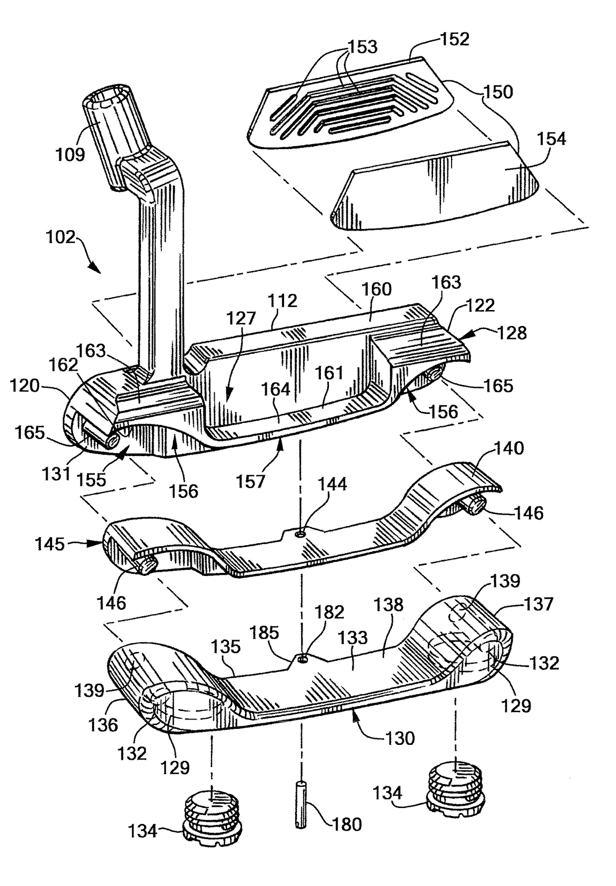
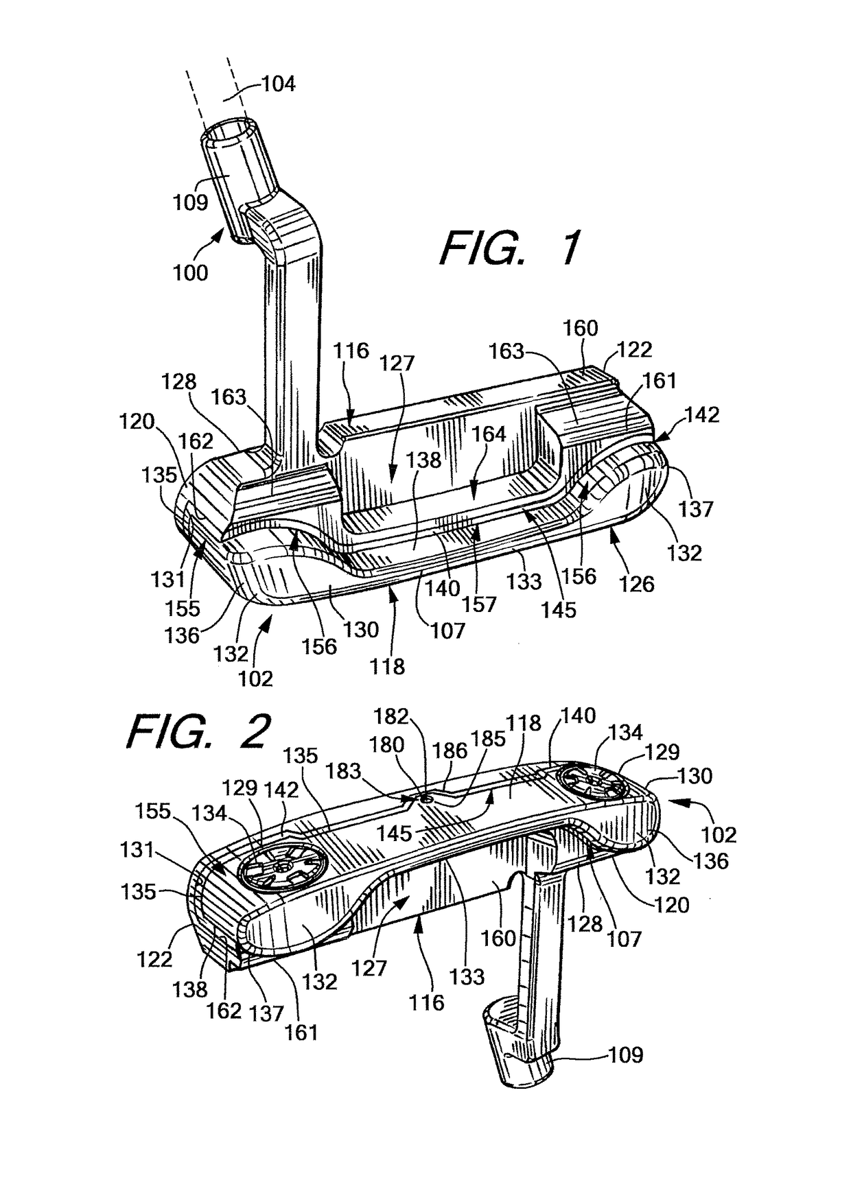
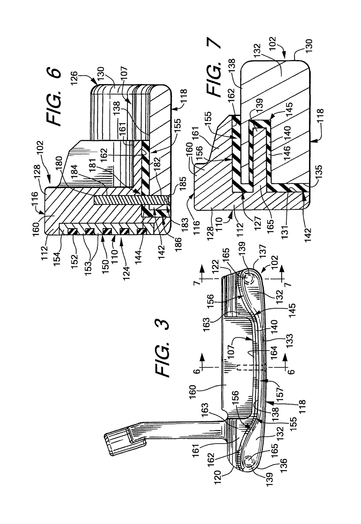
The patent describes a new design for golf club heads that includes a face member and a rear member connected by a resilient material. The resilient material is positioned between the face member and the rear member and is designed to transfer momentum between the two. The face member has projections that engage with the rear member, and the rear member has receivers for the projections. The head also includes a wall that covers at least a portion of the rear member. The technical effects of this design include improved ball striking, reduced weight, and improved stability and accuracy.

Problems solved by technology

Golf clubs and many other ball striking devices can encounter undesirable effects when the ball being struck impacts the ball striking head away from the optimum location, which may be referred to as an “off-center impact.” In a golf club head, this optimum location is, in many cases, aligned laterally and / or vertically with the center of gravity (CG) of the head.
Even slightly off-center impacts can sometimes significantly affect the performance of the head, and can result in reduced velocity and / or energy transfer to the ball, inconsistent ball flight direction and / or spin caused by twisting of the head, increased vibration that can produce undesirable sound and / or feel, and other undesirable effects.

Method used


Image

  • Golf clubs and golf club heads
  • Golf clubs and golf club heads
  • Golf clubs and golf club heads

Examples


Embodiment Construction

[0034]In the following description of various example structures according to the invention, reference is made to the accompanying drawings, which form a part hereof, and in which are shown by way of illustration various example devices, systems, and environments in which aspects of the invention may be practiced. It is to be understood that other specific arrangements of parts, example devices, systems, and environments may be utilized and structural and functional modifications may be made without departing from the scope of the present invention. Also, while the terms “top,”“bottom,”“front,”“back,”“side,”“rear,”“primary,”“secondary,” and the like may be used in this specification to describe various example features and elements of the invention, these terms are used herein as a matter of convenience, e.g., based on the example orientations shown in the figures or the orientation during typical use. Additionally, the term “plurality,” as used herein, indicates any number greater ...


PUM


Abstract

A head for a ball striking device includes a face having a striking surface and a rear side located behind the face, a rear member connected to the rear side of the face member and having a front surface confronting the rear side of the face member, and a resilient material separating the rear member from the face member, such that the resilient member engages the rear member and the face member and is configured to transfer momentum between the face member and the rear member. The face member has projections extending rearwardly from the rear side of the face member proximate the heel and toe sides of the head. The rear member has receivers in the front surface on the heel and toe sides of the head, where the projections are received in the corresponding receivers.

Description

CROSS REFERENCE TO RELATED APPLICATION[0001]This application claims priority to, and is a continuation-in-part of, co-pending U.S. patent application Ser. No. 13 / 308,079, filed Nov. 30, 2011.TECHNICAL FIELD[0002]The invention relates generally to ball striking devices, such as golf clubs and golf club heads, utilizing features for transfer of energy and / or momentum. Certain aspects of this invention relate to golf club heads having a rear member configured to transfer energy and / or momentum to the face upon an impact on the face.BACKGROUND[0003]Golf clubs and many other ball striking devices can encounter undesirable effects when the ball being struck impacts the ball striking head away from the optimum location, which may be referred to as an “off-center impact.” In a golf club head, this optimum location is, in many cases, aligned laterally and / or vertically with the center of gravity (CG) of the head. Even slightly off-center impacts can sometimes significantly affect the perform...

Claims


Application Information

Patent Timeline
Patent Type & Authority Patents(United States)
IPC IPC(8): A63B53/04A63B53/06A63B60/54A63B60/52
CPCA63B53/0487A63B53/04A63B53/047A63B53/0466A63B60/52A63B2209/00A63B2053/045A63B2053/0425A63B2053/0433A63B2053/0491A63B2053/0495A63B60/54A63B53/0425A63B53/045A63B53/0433A63B60/00
Inventor FRANKLIN, DAVID N.KAMMERER, BRIAN
Owner NIKE INC
Learn More