Prosthetic foot with two leaf-springs joined at heel and toe

a technology of prosthetic feet and leaf springs, applied in the field of prosthetic feet, can solve the problems of limited material and imagination in the development of functional and natural artificial feet, inconvenient switching, and the typical unsuitability of particular purposes of feet for other purposes

Active Publication Date: 2009-10-22
FREEDOM INNOVATIONS INC
View PDF99 Cites 25 Cited by
  • Summary
  • Abstract
  • Description
  • Claims
  • Application Information

AI Technical Summary

Benefits of technology

[0010]It has been recognized that it would be advantageous to develop a prosthetic foot with a non-linear force deflection under loading during gait.

Problems solved by technology

With respect to prosthetic feet, the development of a functional and natural artificial foot has been limited only by material and imagination.
Although different prosthetic feet may be changed to suit the particular activity, such switching is inconvenient and at times it is impossible, such as a sudden need to run to catch, or avoid being hit by a bus.
Feet designed for particular purposes are typically unsuited for other purposes.
Stiff, athletic feet are too hard for everyday use, and loose, everyday feet are too fragile for athletic use.
Multiple-use feet have been designed which are capable of many different uses, but without being particularly well suited for any use.

Method used


Image

  • Prosthetic foot with two leaf-springs joined at heel and toe
  • Prosthetic foot with two leaf-springs joined at heel and toe
  • Prosthetic foot with two leaf-springs joined at heel and toe

Examples


Embodiment Construction

)

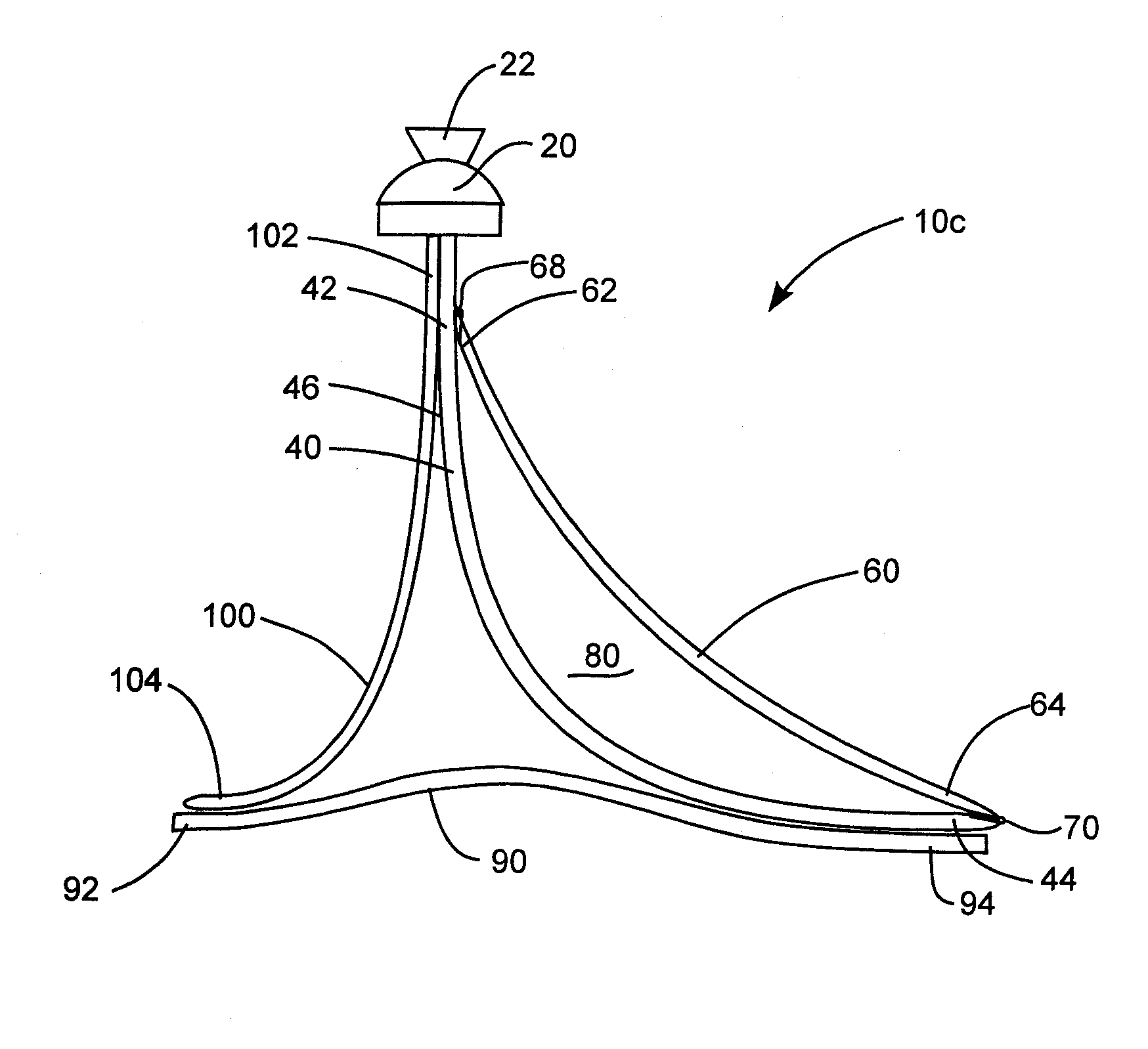
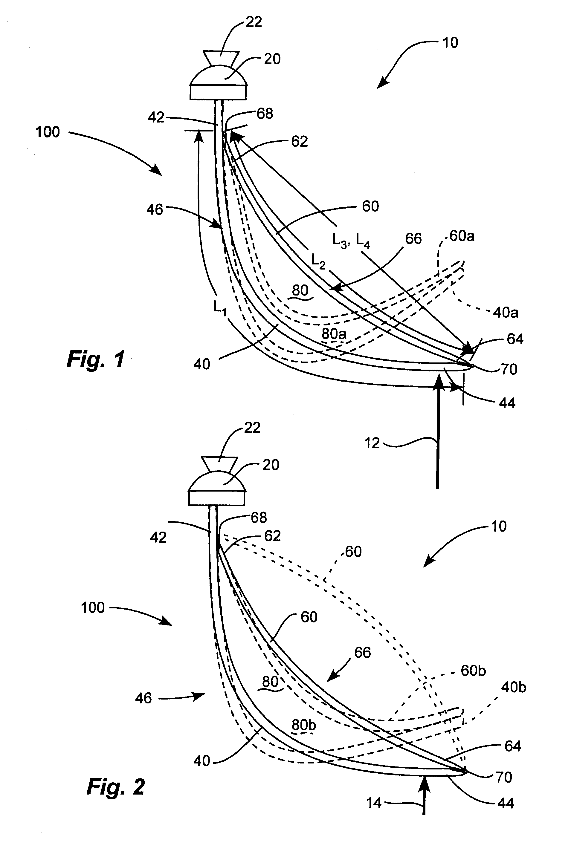
[0022]The embodiments of the present invention generally described herein provide for a prosthetic foot device having a primary lower elongated foot leaf spring and a secondary upper elongated forefoot leaf spring disposed above the lower forefoot leaf spring. The lower forefoot leaf spring can extend from an ankle section positioned at the ankle location of a natural foot downwardly and forwardly to a toe section positioned at the toe location of a natural foot. The lower forefoot leaf spring can be smoothly curved and can form an arc between the ankle section and the toe section. The upper forefoot leaf spring can be coupled to the lower forefoot leaf spring at the ankle section and at the toe location. The leaf springs can be coupled at their proximal and distal ends by hinge connections. The upper forefoot leaf spring can extend in a smooth curve downwardly and forwardly from the ankle location to the toe location and can form an arc between the ankle section and the toe sectio...


PUM


Abstract

A prosthetic foot includes a pair of elongated forefoot leaf springs with proximal ends coupled to an attachment member and extending in an arc to distal ends with the forefoot leaf springs being oriented with one over another. The pair of forefoot leaf springs has different lengths and is coupled to one another at the proximal and distal ends defining an open, uninterrupted gap between the forefoot leaf springs. A pair of hinge connections can be disposed each at a different one of the proximal and distal ends of the pair of elongated forefoot leaf springs. The pair of forefoot leaf springs together has a non-linear force deflection under loading during gait.

Description

PRIORITY CLAIM[0001]Priority is claimed to copending U.S. Provisional Patent Application Ser. No. 61 / 124,687, filed Apr. 18, 2008, which is hereby incorporated herein by reference in its entirety.BACKGROUND[0002]1. Field of the Invention[0003]The present invention relates to a resilient prosthetic foot that has a reinforcement member to provide reinforcement. More particularly, the present invention relates to a prosthetic foot having at least a resilient forefoot member, and at least one resilient reinforcement member.[0004]2. Related Art[0005]Many individuals have lost a limb for various reasons including war, accident, or disease. In most instances these individuals are not only able to live relatively normal lives, but physically active lives as well. Often times, these individuals are aided in their everyday lives by a prosthetic limb. The objective of prosthesis is to provide an artificial limb that simulates the function and natural feel of the replaced limb.[0006]With respec...

Claims


Application Information

Patent Timeline
Patent Type & Authority Applications(United States)
IPC IPC(8): A61F2/66
CPCA61F2/66A61F2002/30359A61F2002/5079A61F2220/0033A61F2002/6671A61F2002/6685A61F2002/665
Inventor CHRITSTENSEN, ROLAND J.
Owner FREEDOM INNOVATIONS INC
Why Eureka
Try Eureka