Input device with dynamic display function

a dynamic display and input device technology, applied in anti-theft devices, instruments, vehicle components, etc., can solve the problems of fingerprints or marks left on the surface of buttons, difficult to prevent the password from being guessed, and the electronic lock with an lcd consumes too much power, so as to prevent fingerprints being left, prevent peeking, and input the same password safe

Inactive Publication Date: 2018-03-06
CHOU SHIH KANG
View PDF1 Cites 0 Cited by
  • Summary
  • Abstract
  • Description
  • Claims
  • Application Information

AI Technical Summary

Benefits of technology

[0009]1. Since the buttons are randomly lit up by the control module in every operation, the users may safely input the same password by touching or pressing a different buttons combination to avoid fingerprints being left on the same buttons and prevent peeking or being secretly recorded by other people.
[0010]2. The present invention consumes less power than the conventional LCD type electronic lock, because the buttons of the present invention are not necessary or seldom all lit up in every operation. The battery may last much longer in the present invention, so it is not necessary to replace the batteries frequently. The present invention does not utilize an LCD and, thus, size and thickness are decreased in the present invention. This may facilitate the present invention being installed on any kind of application such as an electronic safe, a locker or a door lock.

Problems solved by technology

This will lead to fingerprints or marks being left on surfaces of those buttons.
Because certain buttons are always being pressed, it is also hard to prevent the password from being guessed by peeking or being secretly recorded by other persons.
However, the electronic lock with an LCD consumes too much power and needs to be charged or batteries must be changed frequently.

Method used


Image

  • Input device with dynamic display function
  • Input device with dynamic display function
  • Input device with dynamic display function

Examples


first embodiment

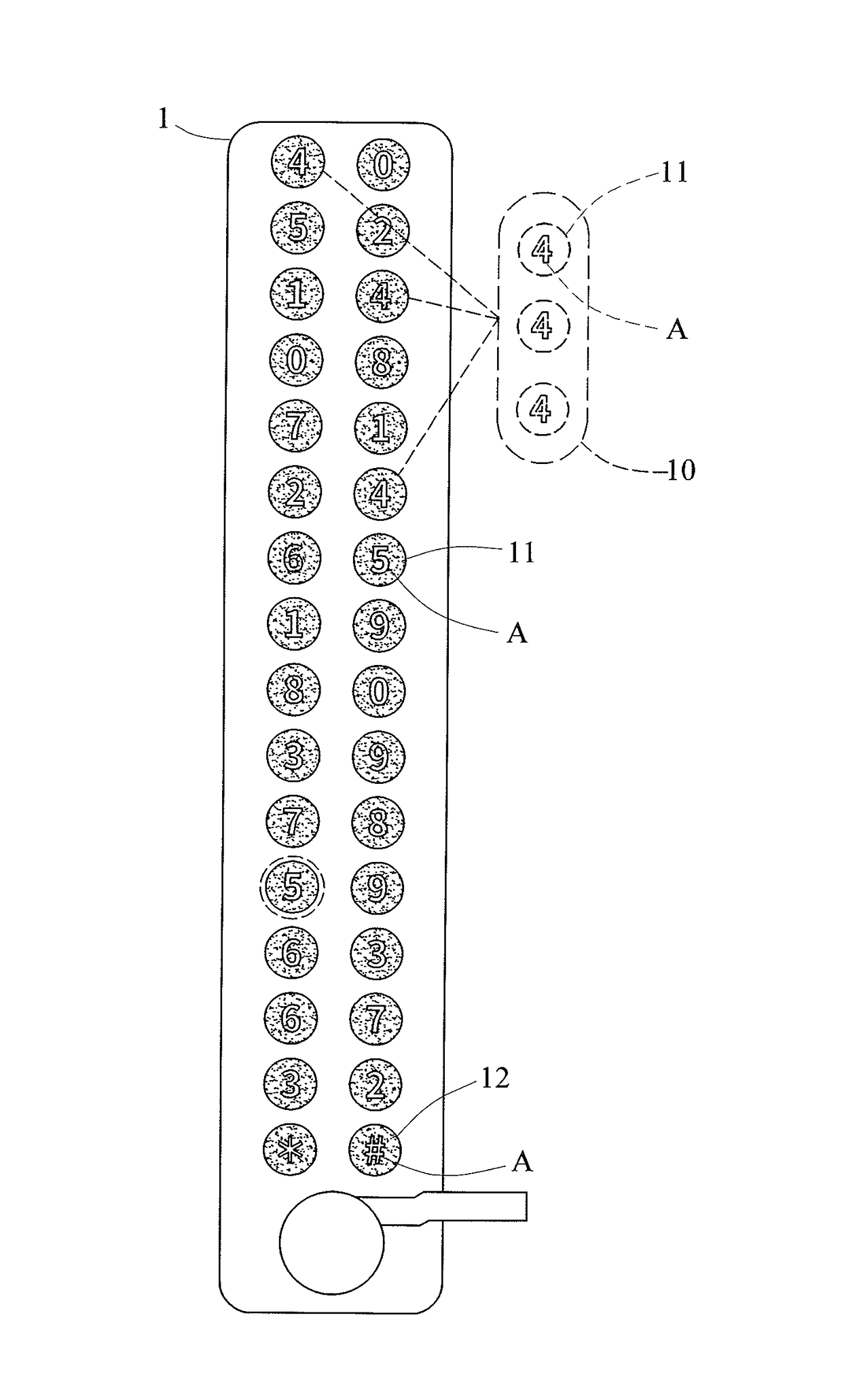
[0023]The panel 1 has at least two button groups 10 and may have an interface unit 2. The at least two buttons groups 10 are located on the panel 1. Each buttons group 10 has at least one button 11. The button 11 in the same buttons group 10 has an identical symbol A marked thereon. The button 11 in a different buttons group 10 is marked with different symbol A. The button 11 may be but not limited to an electrical thin film button, a mechanical button or a define area of a touch panel. In the present invention, ten buttons groups 10 and two special buttons 12 are disclosed. Each buttons group 10 has three buttons 11 marked with the same symbol A. The symbol A of this embodiment are numbers from “0”, “1”. . . to “9” in different buttons groups 10. The buttons 11 mounted on the panel 1 are all translucent for showing the symbol A properly. The buttons 11 having the same symbol A in the same buttons group 10 are randomly placed on the panel 1. Two special buttons 12 are also transluce...

second embodiment

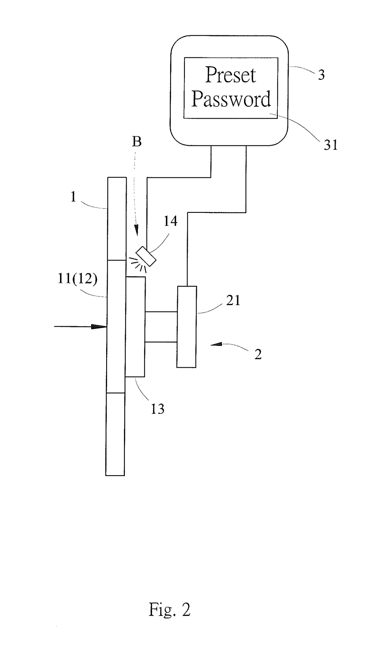
[0025]The interface unit 2 transfers signals when the buttons 11 and the two special buttons 12 are touched by users. In this embodiment, the interface unit 2 has multiple touch units 21, and each touch unit 21 is respectively placed on the back side of each button 11 and the two special buttons 12. Thus, each touch units 21 is able to transfer the signal when the buttons 11 or the two special buttons 12 are touched by the users. The touch unit 21 may be but not limited to a switch or a sensor on a printed circuit board (PCB). With reference to FIG. 3, the present invention is presented. The touch units 21 of the interface unit 2 are sensors on the PCB. The sensors may be proximity sensors or touch sensors placed on the back side of each button 11 and the two special buttons 12. The interface unit 2 may not be necessary in this invention if the buttons 11 and the two special buttons 12 are connected to the control module 3.

[0026]With reference to FIG. 1, FIG. 3, FIG. 4, and FIG. 5, ...

third embodiment

[0028]The panel 1 has at least two buttons groups 10 mounted thereon. The numbers of the buttons 11 is at least one in every buttons groups 10, but one of the buttons group 10 has at least two buttons 11. With reference to FIG. 6, the present invention is presented. The buttons groups 10 having the button 11 marked with symbols A of “0”, “1”, “2”, “3”, “6” and “7” only have one button 11 therein. The buttons groups 10 having the button 11 marked with symbols A of “4”, “5”, “8” and “9” otherwise have two buttons 11 therein. The arrangement of the buttons groups 10 in this embodiment may reduce the numbers of buttons 11 mounted on the panel 1 in order to minimize the size of the panel 1. The control module 3 still can randomly light up one button 11 in different buttons groups 10 marked with symbols A of “0” to “9” and two special buttons 12 for the users to input the password properly.

[0029]Since the buttons 11 are randomly lit up by the control module 3 in every operation, the users...


PUM


Abstract

An input device with a dynamic display function includes a panel, an interface unit, and a control module, with multiple buttons groups randomly mounted on the panel. Each buttons group has at least one button, and one buttons group has at least two buttons. Every button has a lighting unit placed adjacently and has a symbol marked thereon, and the buttons in the same buttons groups have an identical symbol. The control module is electrically connected with the interface unit and the lighting unit and lights up at least one lighting unit and its corresponding button in every buttons groups. The interface unit transfers a signal from the lit button when the button is triggered. The buttons are randomly lit up by the control module in every operation.

Description

BACKGROUND OF THE INVENTION[0001]1. Field of the Invention[0002]The present invention is related to an input device and, especially, to an input device with a dynamic display function.[0003]2. Description of the Prior Art[0004]A lock is an old invention for protecting people's properties and physical safety. A traditional key-lock pair is improved as a key-less electronic lock to prevent a duplicate of a stolen key. A conventional electronic lock has buttons to input a preset password for unlocking. The buttons usually contain ten digital numbers from “0” to “9” being sequentially placed at a fixed position on the electronic lock. Since the buttons are fixed, the lock owner always presses the same buttons when inputting the password. This will lead to fingerprints or marks being left on surfaces of those buttons. Thus, the password of the electronic lock becomes easy to guess by other persons if they try to break into the lock owner's properties. Because certain buttons are always b...

Claims


Application Information

Patent Timeline
Patent Type & Authority Patents(United States)
IPC IPC(8): B60R25/00G07C9/00G06F3/041
CPCG07C9/00817G06F3/041G07C9/00174G07C2009/00642G07C9/0069
Inventor CHOU, SHIH-KANG
Owner CHOU SHIH KANG
Why Eureka
Try Eureka