Input Device with Dynamic Display Function
a dynamic display and input device technology, applied in the field of input devices, can solve the problems of wasting power, affecting the accuracy of input and output, and requiring frequent charging or changing of batteries, so as to prevent other people from peeking or secretly recording, avoiding fingerprints or marks on the surface of input buttons, and safe input of same password
- Summary
- Abstract
- Description
- Claims
- Application Information
AI Technical Summary
Benefits of technology
Problems solved by technology
Method used
Image
Examples
first embodiment
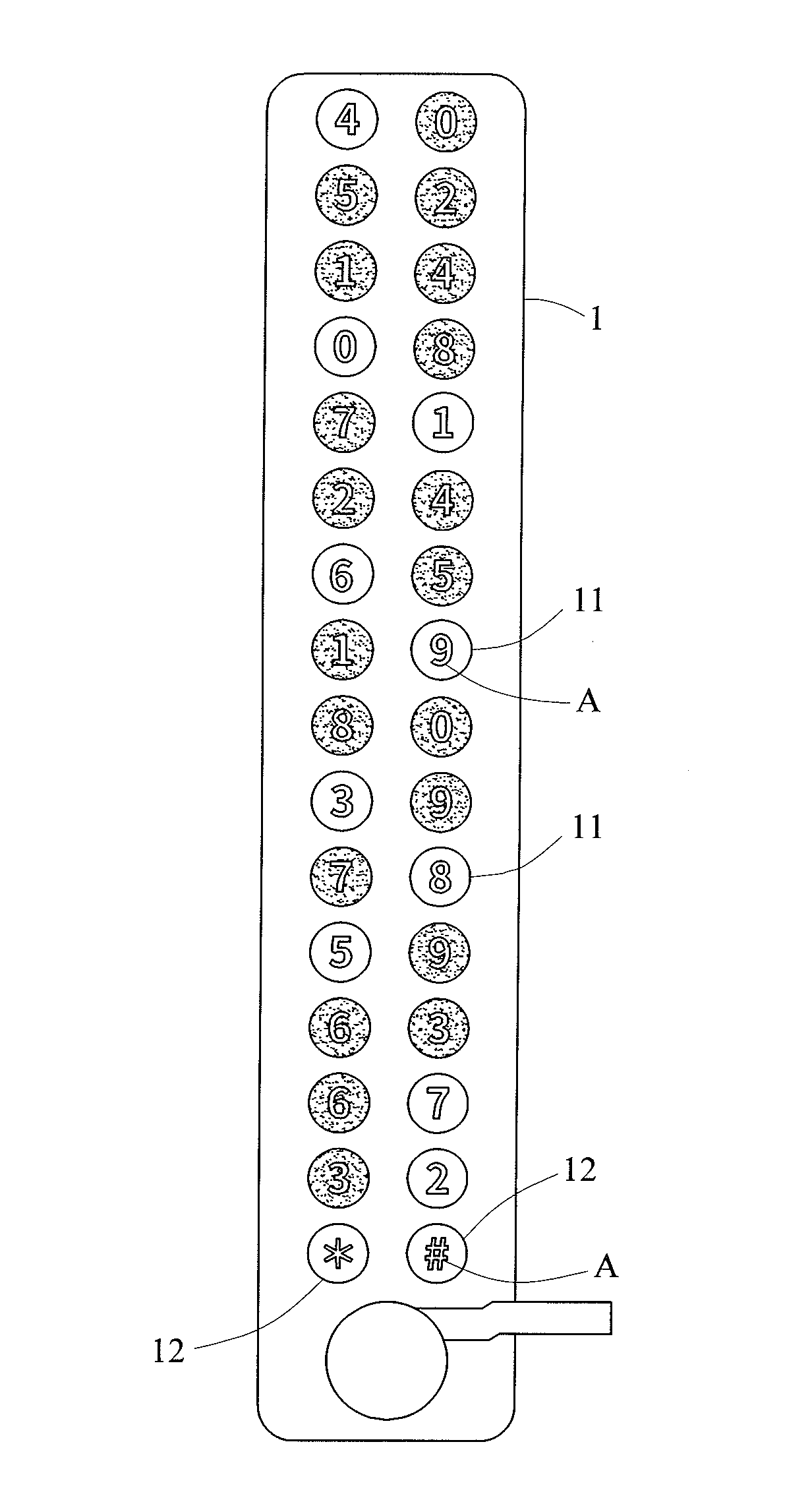
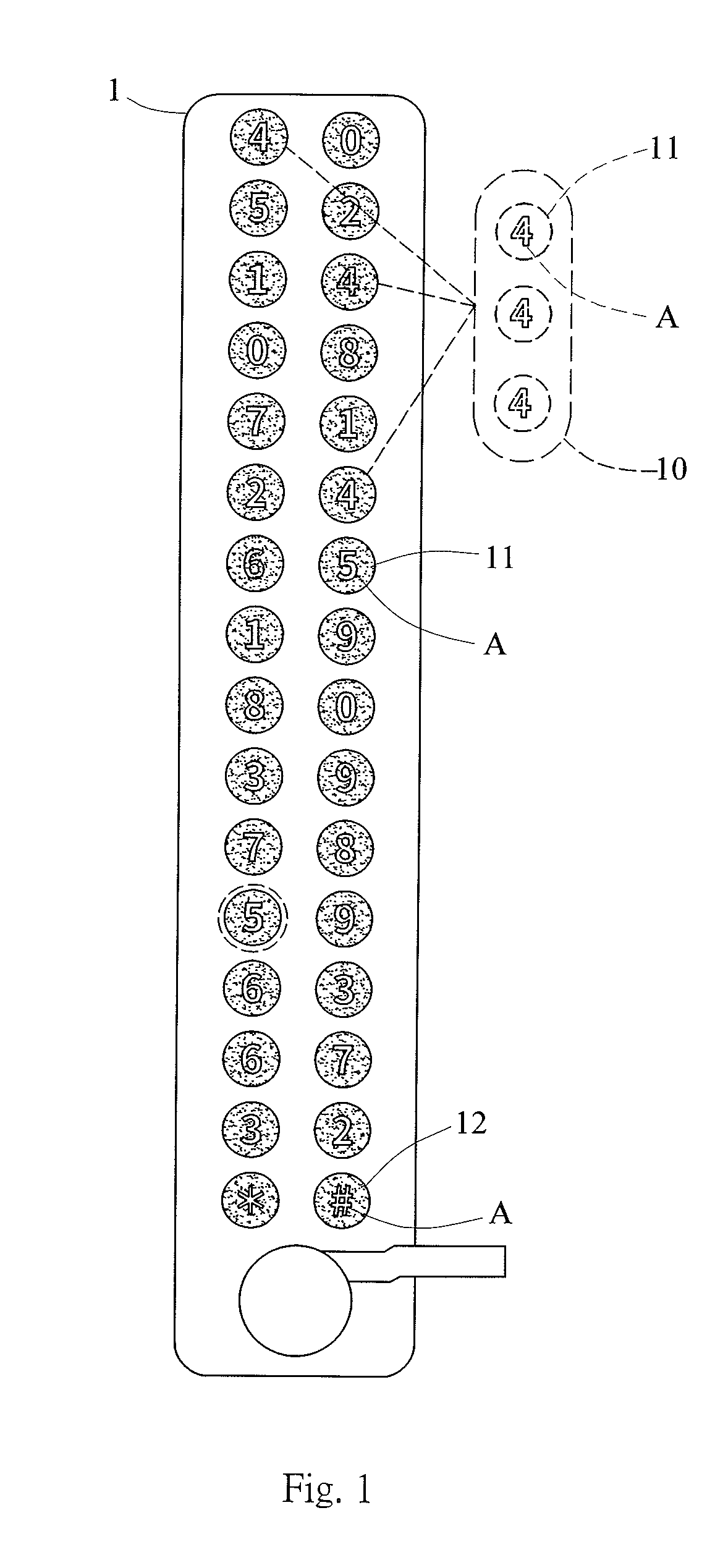
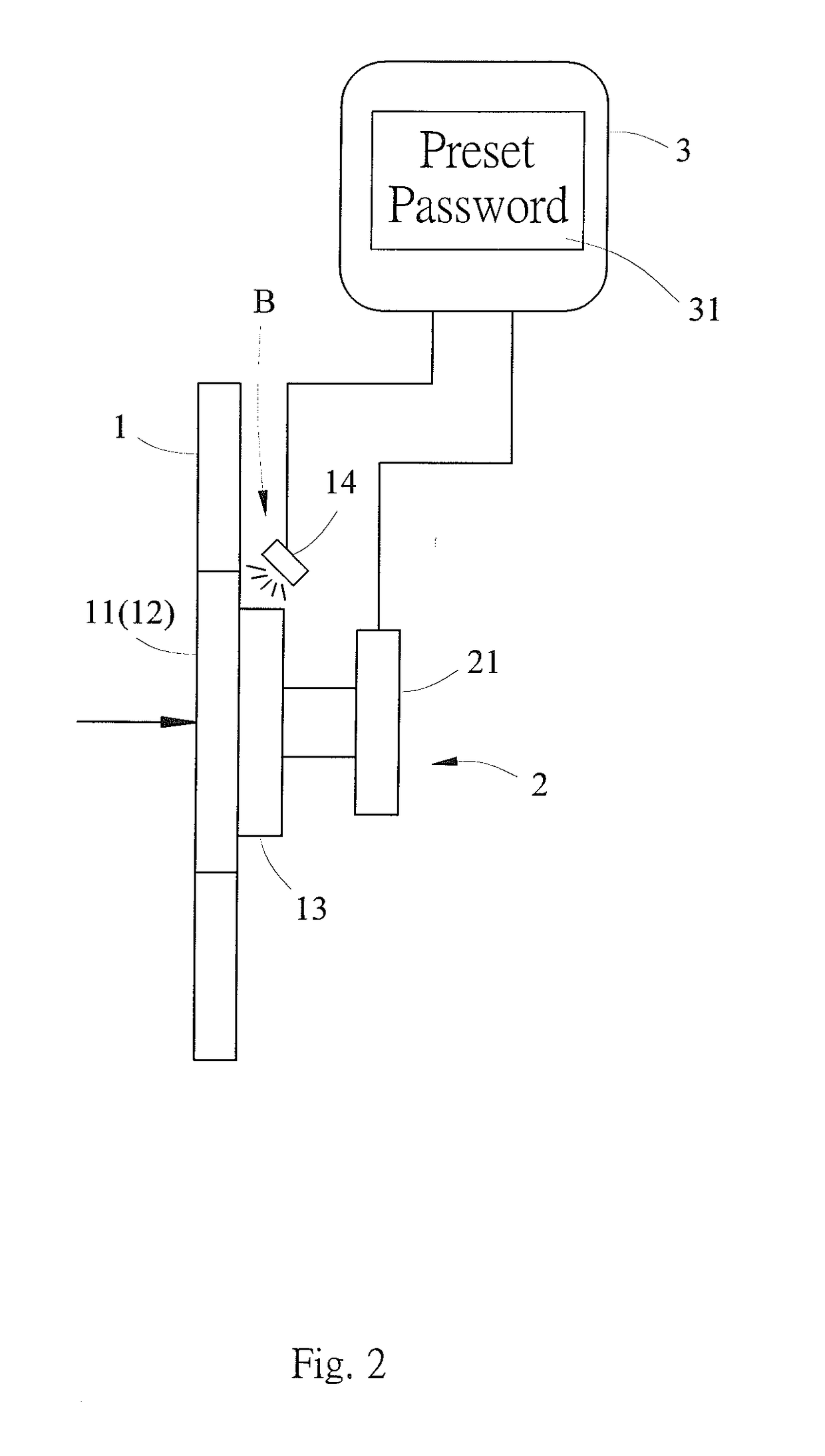
[0022]With reference to FIG. 1 and FIG. 2, an input device with dynamic display function may be used for electronic safe, electronic lock, automated teller machine (ATM) and the like applications in accordance with the present invention comprising a panel 1 and a control module 3 being electrically connected to the panel 1. The panel 1 has at least two button groups 10 and may have an interface unit 2. The at least two buttons groups 10 are located on the panel 1. Each buttons group 10 has at least one button 11. The button 11 in same buttons group 10 has identical symbol A marked thereon. The button 11 in different buttons group 10 is marked with different symbol A. The button 11 may be but not limited to an electrical thin film button, a mechanical button or a define area of a touch panel. In the present invention, ten buttons groups 10 and two special buttons 12 is disclosed. Each buttons group 10 has three buttons 11 marked with the same symbol A. The symbol A of this embodiment...
second embodiment
[0024]The interface unit 2 transfers signals when the buttons 11 and the two special buttons 12 are touched by users. In this embodiment, the interface unit 2 has multiple touch units 21, and each touch unit 21 is respectively placed on the back side of each button 11 and the two special buttons 12. Thus, each touch units 21 is able to transfer the signal when the buttons 11 or the two special buttons 12 are touched by the users. The touch unit 21 may be but not limited to a switch or a sensor on a printed circuit board (PCB). With reference to FIG. 3, the present invention is presented. The touch units 21 of the interface unit 2 are sensors on PCB. The sensors may be proximity sensors or touch sensors placed on the back side of each buttons 11 and the two special buttons 12. The interface unit 2 may not be necessary in this invention if the buttons 11 and special buttons 12 are connected to the control module3.
[0025]With reference to FIG. 1, FIG. 3, FIG. 4, and FIG. 5, the control ...
third embodiment
[0027]The panel 1 has at least two buttons groups 10 mounted thereon. Numbers of the buttons 11 are at least one in every buttons groups 10, but one of the buttons group 10 has at least two buttons 11. With reference to FIG. 6, the present invention is presented. The buttons groups 10 having the button 11 marked with symbols A of “0”, “1”, “2”, “3”, “6” and “7” only have one button 11 therein. The buttons groups 10 having the button 11 marked with symbols A of “4”, “5”, “8” and “9” are otherwise have two buttons 11 therein. Arrangement of the buttons groups 10 in this embodiment may reduce the numbers of buttons 11 mounted on the panel 1 in order to minimize the size of the panel 1. The control module 3 still can randomly lit up one of the button 11 in different buttons groups 10 marked with symbols A of “0” to “9” and two special buttons 12 for the users to input the password properly.
[0028]Since the buttons 11 are randomly lit up by the control module 3 in every operation, the use...
PUM
 Abstract
Description
Claims
Application Information
 - R&D
- Intellectual Property
- Life Sciences
- Materials
- Tech Scout
- Unparalleled Data Quality
- Higher Quality Content
- 60% Fewer Hallucinations
Browse by: Latest US Patents, China's latest patents, Technical Efficacy Thesaurus, Application Domain, Technology Topic, Popular Technical Reports.
© 2025 PatSnap. All rights reserved.Legal|Privacy policy|Modern Slavery Act Transparency Statement|Sitemap|About US| Contact US: help@patsnap.com


