Presence indication in a wireless communication system
a wireless communication system and presence indication technology, applied in the field of wireless communication systems, can solve the problems of enodeb collision risk and architecture not flexible to the changing u
- Summary
- Abstract
- Description
- Claims
- Application Information
AI Technical Summary
Benefits of technology
Problems solved by technology
Method used
Image
Examples
first embodiment
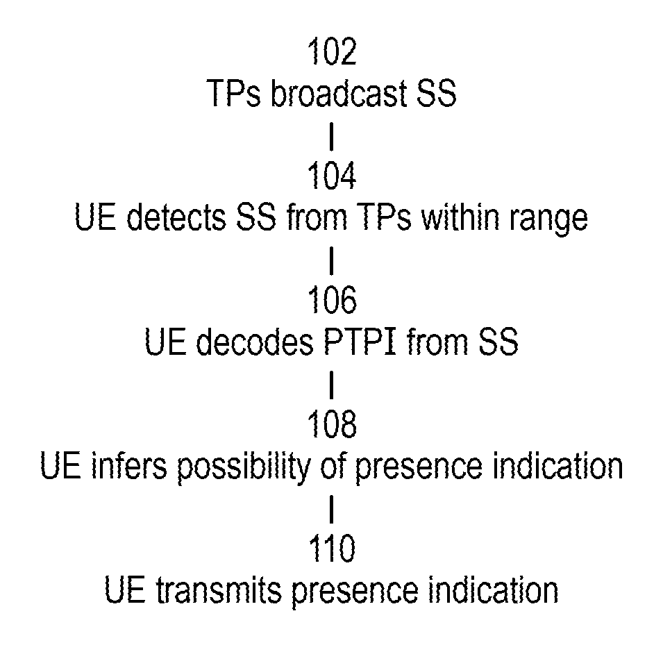
[0119]In a first embodiment, the set of participating TPs transmit their SSs carrying PTPIs. Each PTPI is characteristic of a particular TP, although each TP is not necessarily restricted to a single PTPI. Other broadcast signals are not necessarily transmitted. A UE which is able to receive a particular PTPI can treat this as permission to transmit SRS according to a given configuration in a particular subframe number m, thus indicating its presence to the network. A set of UE-specific SRS configurations could be reserved in specifications to be used for this purpose as distinct from the convention UL channel sounding usage of SRS. Multiple UEs transmitting in the same UE-specific SRS configuration could be distinguished by having different cyclic shifts on their SRS sequences. However, it may not be necessary for the network to be able to identify exactly how many UEs have indicated their presence at a given moment.
[0120]In the case that the SSs are in fact the LTE PSS and SSS car...
second embodiment
[0123]A second embodiment is like the first, except that permission is given to the UE for a transmission on PRACH. To distinguish conventional uses of PRACH from this invention, a subset of the RA preambles could be reserved to be used for this purpose. In the case of a UE operating in a scenario of not having an RRC connection to the network and / or no access to PBCH transmissions (see later embodiments), a portion of PRACH resources could be reserved in specifications for transmission of similarly reserved RA preambles for the purpose of this invention. On receiving a RA preamble relevant to this embodiment, the network does not engage in the usual RA procedure, but may instead follow a course of action such as those described in the following embodiments.
[0124]If more than one UE selects the same preamble in this embodiment, they will simply both be received by the network in the same subframe. This will ‘hide’ the true quantity of UEs but will still provide an indication that th...
fourth embodiment
[0129]On the other hand, the presence indication may be constituted by the combination of the SRS and PRACH rather than by either one individually. Such a combination of signals permits a larger number of possible states to be signalled, for example to allow a larger number of UEs to be distinguished, or to indicate additional information along the lines stated below for the
(d) Multiple UL subframe grants for UE indication
[0130]In this fourth embodiment, the subframe number m in the preceding embodiments is extended to allow multiple subframes {m1, m2, . . . } in which a UE may transmit the signal representing a presence indication. The UE's choice of which particular subframe is used indicates information to the network about the UE's view of the TP such as:[0131]Preferred status of the TP among those being received. For example, a ‘high’ preference would indicate that (i) the UE can receive the TP and (ii) that among those it can receive it would prefer further transmissions on, e...
PUM
 Abstract
Description
Claims
Application Information
 - R&D
- Intellectual Property
- Life Sciences
- Materials
- Tech Scout
- Unparalleled Data Quality
- Higher Quality Content
- 60% Fewer Hallucinations
Browse by: Latest US Patents, China's latest patents, Technical Efficacy Thesaurus, Application Domain, Technology Topic, Popular Technical Reports.
© 2025 PatSnap. All rights reserved.Legal|Privacy policy|Modern Slavery Act Transparency Statement|Sitemap|About US| Contact US: help@patsnap.com


