Compact weight lifting machine

a weight lifting machine and compact technology, applied in the field of physical fitness boom, can solve problems such as bidirectional activation

Inactive Publication Date: 2002-04-09
FULKS KENT
View PDF16 Cites 13 Cited by
  • Summary
  • Abstract
  • Description
  • Claims
  • Application Information

AI Technical Summary

Problems solved by technology

Restraining members allow movement of one arm at a time, but are anchored to limit pivotal movement toward the other arm, resulting in bidirectional activation of the lift cable by the lift bar.

Method used


Image

  • Compact weight lifting machine
  • Compact weight lifting machine
  • Compact weight lifting machine

Examples


Embodiment Construction

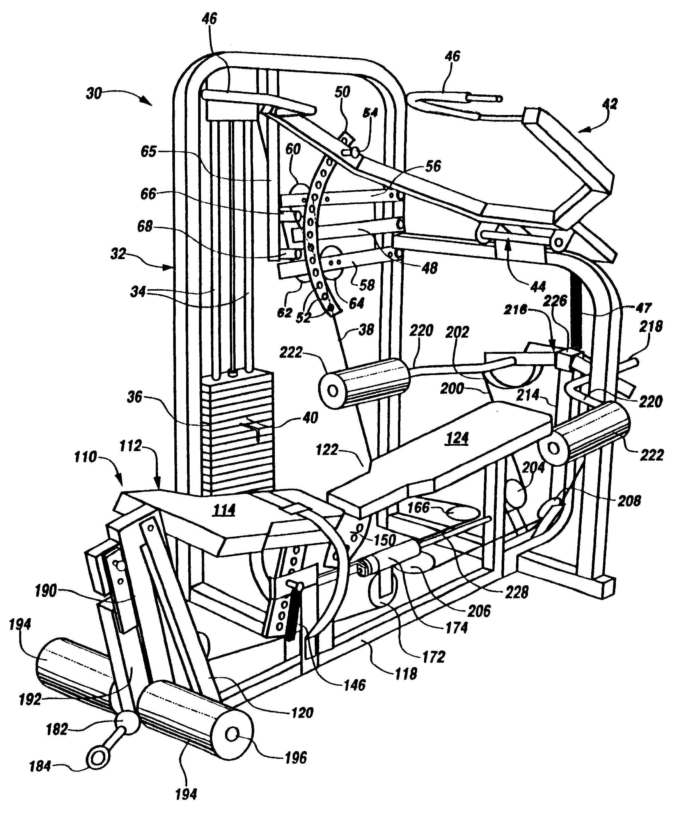
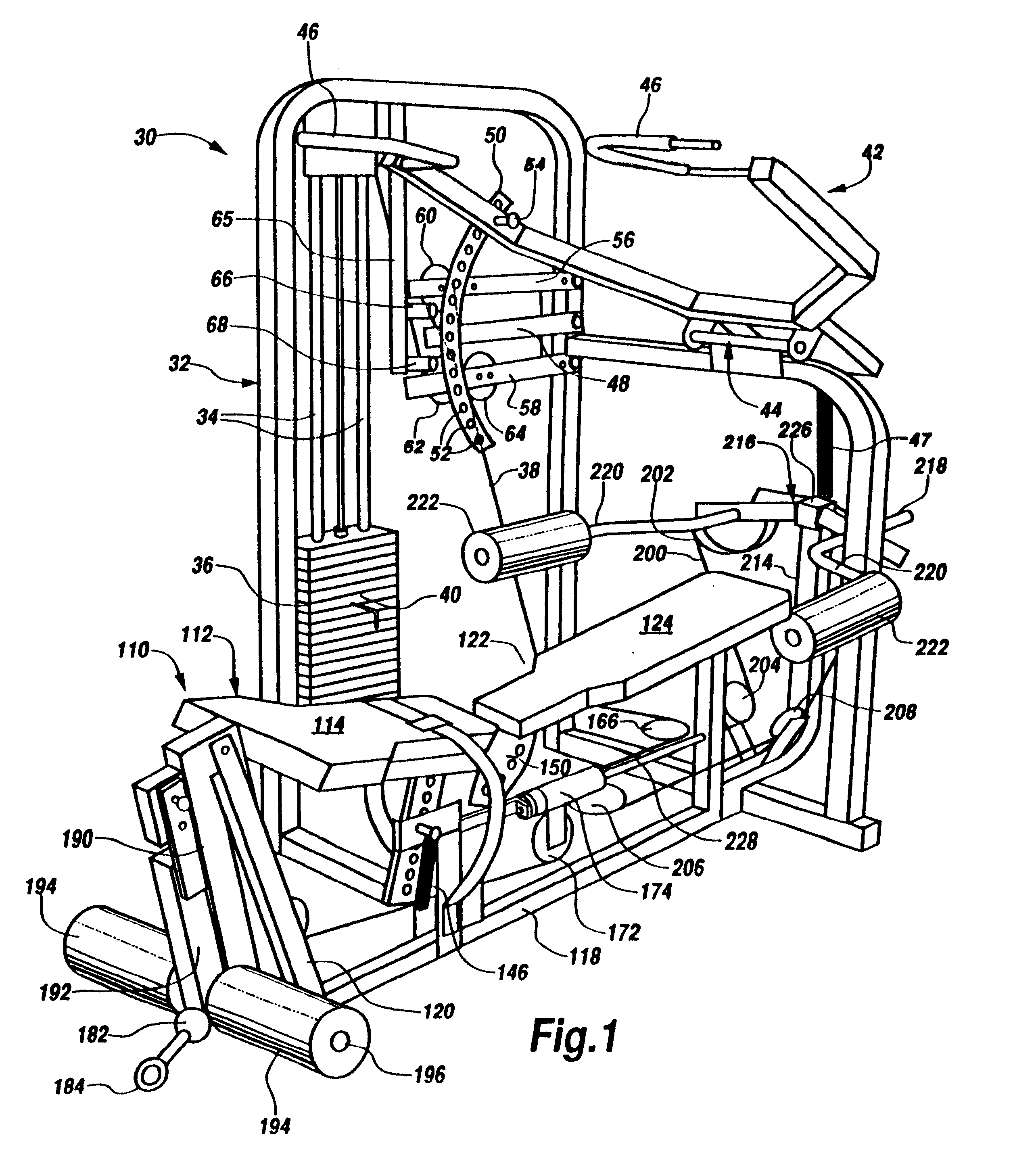
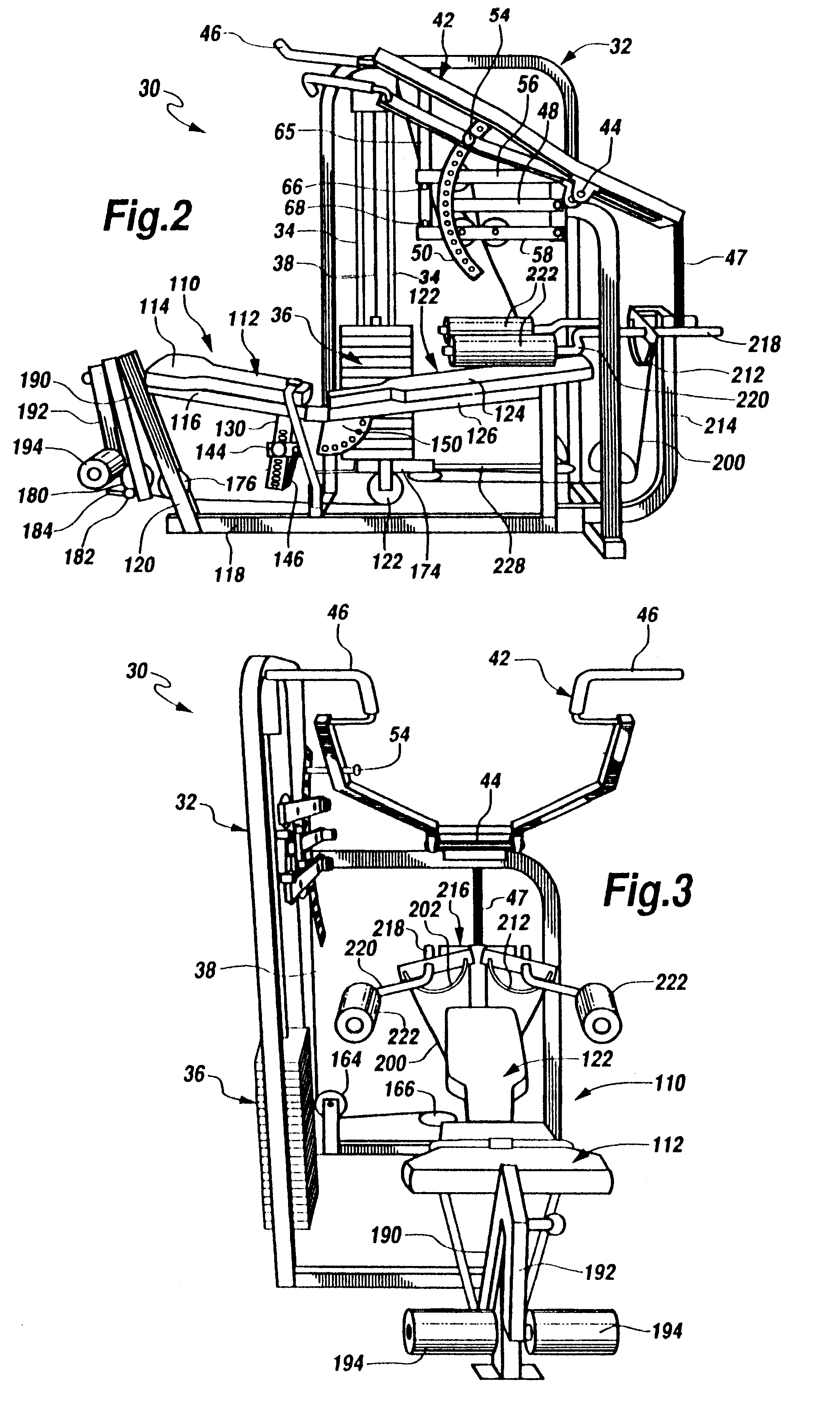
Referring now to the Drawings, and particularly to FIGS. 1, 2 and 3 thereof, there is shown a compact weight lifting machine 30 incorporating the present invention. The machine 30 comprises a frame 32 which supports and positions the various component parts thereof. The frame 32 is conventional in nature and comprises a plurality of interconnected sections of tubing. The tubing sections comprising the frame 32 may be formed from stainless steel or other conventional materials, and may have a square, rectangular, or any other desired cross sectional configuration. The tubing sections comprising the frame 32 are preferably cut, bent, and welded or otherwise secured together using conventional techniques.

The frame 32 includes a pair of vertically extending guides 34. A conventional weight stack 36 comprises a plurality of individual weights which may be formed from cast iron and which are slidably supported on the guides 34 for vertical movement thereon against the action of gravity. A...


PUM


Abstract

A compact weight lifting machine includes a lift bar assembly including a lift cable and a lift bar which operates through the lift cable to lift selected weights from a weight stack responsive to either upward or downward movement of the lift bar. A seat assembly is positioned beneath the lift bar and includes first and second sections selectively positionable to support a user to perform a variety of exercises. A leg extension / leg curl mechanism located at one end of the seat assembly and a butterfly mechanism located at the opposite end of the seat assembly also operate through the lift cable to lift selected weights from the weight stack.

Description

BACKGROUND OF THE INVENTIONWith the advent of the physical fitness boom, weight lifting machines of all shapes and sizes appeared on the market. Unfortunately, each machine typically provides for a very limited range of exercises, requiring several machines to accomplish a full workout.Various means of resistance have been employed in the many different types of prior art weight lifting machines. Hydraulic and pneumatic resistance, as well as cable supported lead weight resistance have been employed, with the traditional lead weight resistance machines exhibiting greater durability. In lead weight-type machines the weight stack is usually suspended from a cable and structure is provided for incrementally adjusting the amount of weight being lifted. Typically, the cable is configured over a series of pulleys for extension and retraction in a single direction. Therefore, movement of the weight lifting bar or lever connected to the opposite end of the lift cable is restricted to a part...

Claims


Application Information

Patent Timeline
Patent Type & Authority Patents(United States)
IPC IPC(8): A63B23/00A63B21/062A63B21/06A63B21/00A63B23/12A63B23/035
CPCA63B21/00072A63B21/154A63B23/00A63B23/03525A63B23/03533A63B23/03541A63B23/03566A63B23/12A63B23/1209A63B23/1254A63B23/1263A63B21/0628A63B21/4029A63B21/4035A63B21/4047
Inventor FULKS, KENT
Owner FULKS KENT
Why Eureka
Try Eureka