
Component coder and coding method, double-output Turbo coder and coding method
A component encoding and encoder technology, applied in the component encoder and its encoding method, and the dual-input turbo encoder and its encoding field, can solve the problems of increasing the length of the encoding block, ignorance, and increasing the decoding complexity, etc. Reduce the amount of encoding calculation, reduce the encoding delay, and avoid the effect of the encoding process
- Summary
- Abstract
- Description
- Claims
- Application Information
AI Technical Summary
Problems solved by technology
Method used
Image

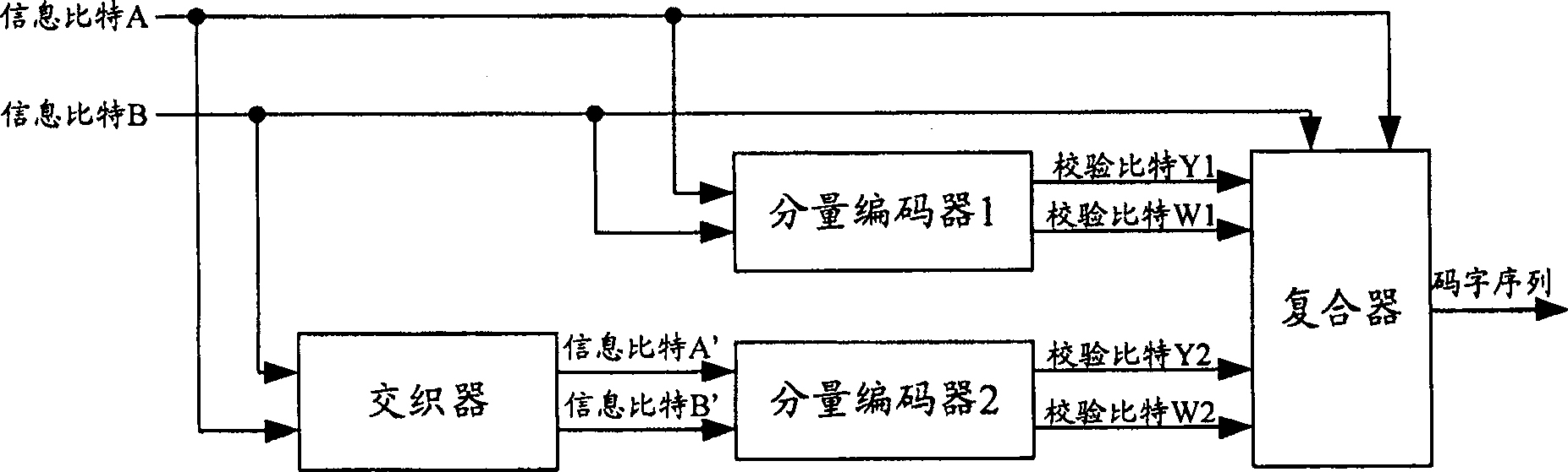

Examples
Embodiment Construction
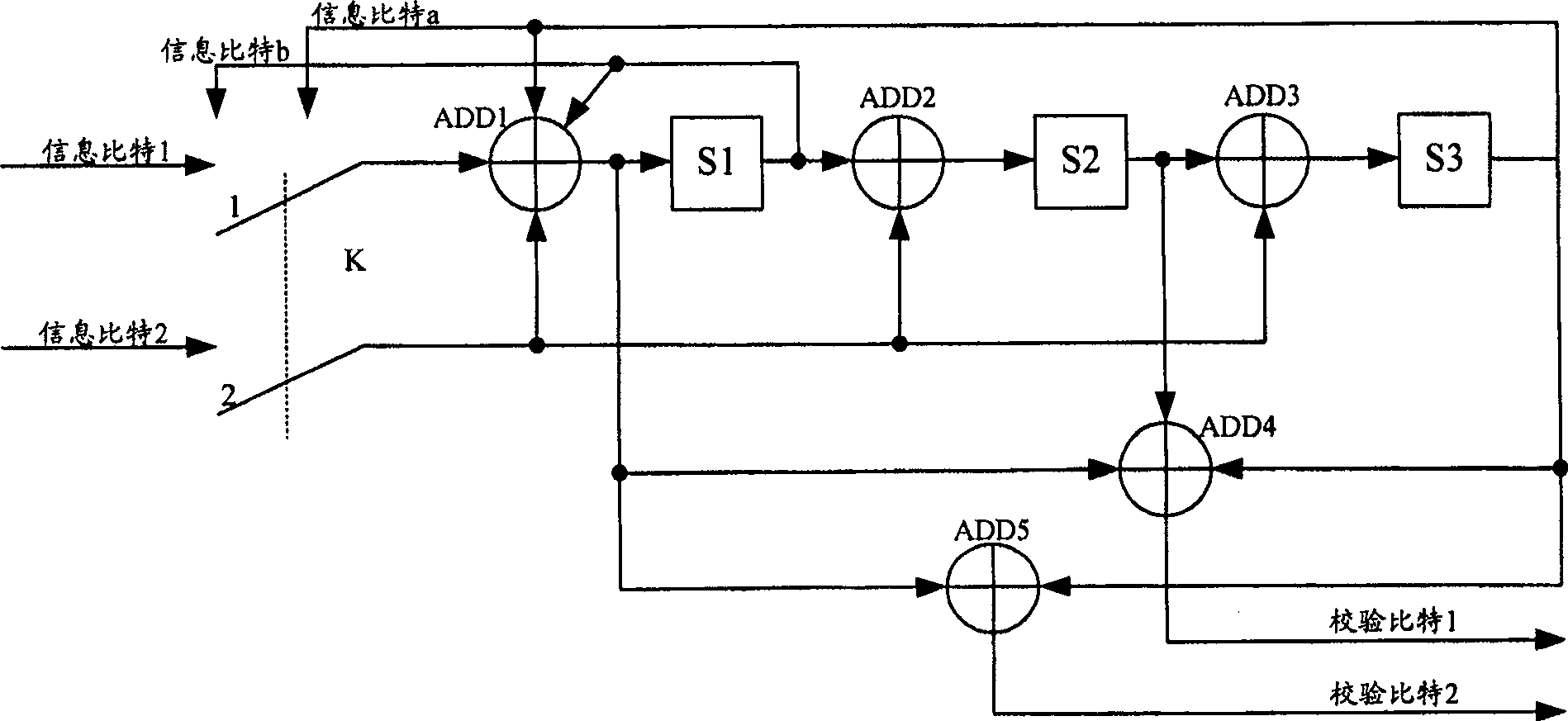
[0061] The core idea of the present invention is: set the initial state of the register in the component encoder to zero state, after the component encoder completes the encoding of each coding block, use the feedback bit output by the component encoder's own register to make the component encoder The end state of the register is the zero state.
[0062] In order to make the object, technical solution and advantages of the present invention clearer, the present invention will be further described in detail below with reference to the accompanying drawings and preferred embodiments.
[0063] image 3 is the principle diagram of the composition of the component encoder of the present invention, such as image 3 As shown, the component encoder of the present invention is composed of registers S1-S3, adders ADD1-ADD5 and control switch k, information bit 1 and information bit 2 are two input information bits, check bit 1 and check bit 2 are Check bits that are output after two...
PUM
 Abstract
Description
Claims
Application Information