Thermal fatigue test device of piston

A test device and thermal fatigue technology, applied in the direction of measuring device, mechanical component testing, machine/structural component testing, etc. The effect of consistent temperature status and guaranteed reliability

Inactive Publication Date: 2018-04-17
ZHEJIANG UNIV
View PDF5 Cites 5 Cited by
  • Summary
  • Abstract
  • Description
  • Claims
  • Application Information

AI Technical Summary

Problems solved by technology

[0003] In the existing piston thermal fatigue test device, the tested piston is usually in a free state. When thermal deformation occurs, no thermal stress in line with the actual working conditions is generated. Only the internal thermal stress of the piston is considered, which reduces the possibility of fatigue testing. Reliability
At the same time, the cooling of the existing piston thermal fatigue test device is usually external cooling, and the piston head is cooled by means of external water spray or air jet. Inconsistent cooling methods will lead to errors between the thermal fatigue life obtained in the test and the actual thermal fatigue life
In addition, the existing piston thermal fatigue test devices are relatively fixed in structure, and most of them can only test a single piston, while the devices that can test multiple pistons at the same time cannot flexibly adjust the number of pistons to be tested, and there is a waste of testing resource situation, failed to achieve good resource utilization, increased test costs

Method used


Image

  • Thermal fatigue test device of piston
  • Thermal fatigue test device of piston
  • Thermal fatigue test device of piston

Examples


Embodiment Construction

[0026] The specific implementation manners of the present invention will be described in detail below in conjunction with the accompanying drawings, but it is not intended to limit the present invention.

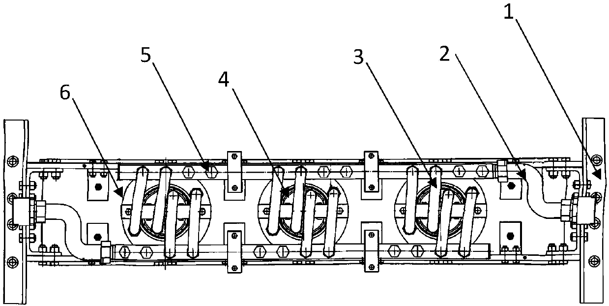
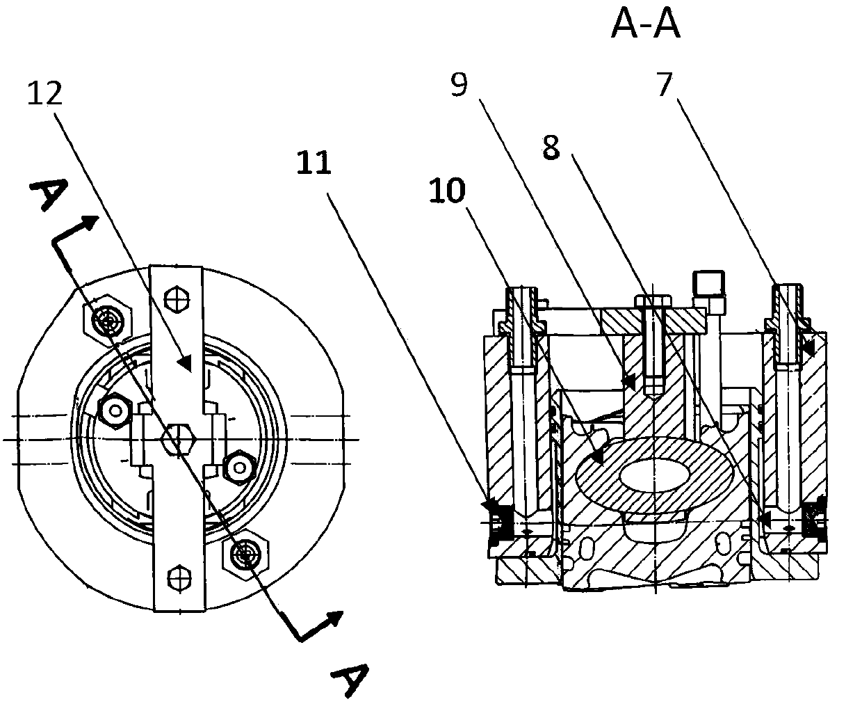
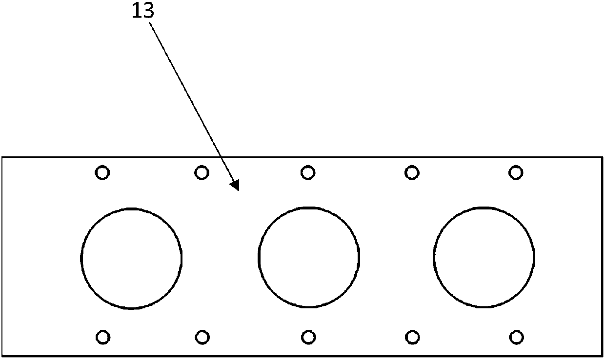
[0027] Such as Figure 1-3As shown, a piston thermal fatigue test device includes a support frame 1 and a non-standard piston tooling 6 arranged on the support frame 1, a tested piston 4, a cooling water branch pipe 3, a heat shield, and a cooling water main pipe 2; After the test piston 4 is assembled with the piston ring, put it into the non-standard piston tooling 6. The cooling water main pipe 2 includes the cooling water inlet main pipe and the cooling water outlet main pipe. Some of the water inlets and outlets of the external thread are connected to the cooling water branch pipe 3, and the remaining water inlets and outlets of the external thread are sealed by the internal thread plug 5. Both the non-standard piston tooling and the tested piston have a cooling water i...


PUM


Abstract

The invention discloses a thermal fatigue test device of a piston. The thermal fatigue test device is composed of a support frame, a non-standard piston tool, a tested piston, branch cooling water pipes, a thermal insulation board, and a main cooling water pipe. With the non-standard piston tool, the mechanical constraint of the tested piston on actual assembling condition is simulated completely;on the basis of cooperation of the cooling pipes, the thermal insulation board, and an external heating device, the temperature field of the tested piston on the actual working condition is simulatedcompletely. Thermal fatigue testing of pistons with different numbers is realized by flexible cooperation of the support frame and the tool. With the thermal fatigue test device disclosed by the invention, the actual assembling condition and cooling environment of the piston can be simulated fully; the arrangement condition can be adjusted flexibly based on the number of the tested pistons; the progress of the thermal fatigue test of the piston is controlled reasonably; the usage energy is optimized; and the credibility of the thermal fatigue test result of the piston is enhanced substantially.

Description

technical field [0001] The invention belongs to the technical field of engine detection, in particular to a piston thermal fatigue test device. Background technique [0002] The piston is one of the parts with the worst working conditions in the engine. With the improvement of engine strengthening, especially the popularization and development of supercharging and other technologies, the thermal load and mechanical load of the piston are increasing, which directly affects its service life. . In order to better develop and design the piston, it is necessary to accurately evaluate the thermal state and thermal fatigue reliability of the piston during work. [0003] In the existing piston thermal fatigue test device, the tested piston is usually in a free state. When thermal deformation occurs, no thermal stress in line with the actual working conditions is generated. Only the internal thermal stress of the piston is considered, which reduces the possibility of fatigue testing...

Claims


Application Information

Patent Timeline
Patent Type & Authority Applications(China)
IPC IPC(8): G01M13/00
CPCG01M13/00
Inventor 韩开韦刘震涛沈瑜铭
Owner ZHEJIANG UNIV
Why Eureka
Try Eureka