Method for measuring flow parameter distribution in particle flow two-phase flow reactor

A technology of flow parameters and reactors, applied in fluid dynamics experiments, measuring devices, instruments, etc., can solve the problems of only paying attention to, not considering the influence of cross-scale correlation on mesoscopic structure, difficult selection of sample space, etc.

Inactive Publication Date: 2009-08-05
INST OF PROCESS ENG CHINESE ACAD OF SCI
View PDF6 Cites 0 Cited by
  • Summary
  • Abstract
  • Description
  • Claims
  • Application Information

AI Technical Summary

Problems solved by technology

This static, empirical estimation method is inherently unable to extrapolate from the original experimental conditions to industrial reactors
[0008] Existing works have only paid attention to the influence of substructure microscale on mesostructure (see reference 3: Agrawal, K., Loezos, P.N., Syamlal, M., Sundaresan, S.Journal of Fluid Mechanics.Vol.445, P .151.(2001)), trying to directly correlate the effect of complex mesoscopic structure on drag force from the calculation results of the sample micro-element space, without considering the influence of cross-scale correlation on mesoscopic structure
The sample space of the actual process is difficult to choose, and it is not feasible in the application of industrial reactors

Method used


Image

  • Method for measuring flow parameter distribution in particle flow two-phase flow reactor
  • Method for measuring flow parameter distribution in particle flow two-phase flow reactor
  • Method for measuring flow parameter distribution in particle flow two-phase flow reactor

Examples


Embodiment 1

[0108] Example 1 The method of the present invention is applied to flow prediction in a fast fluidized calciner for coal-based kaolin with an annual output of 1,000 tons. The average particle size of raw material kaolin is 0.002mm, and the particle density is 800kg / m 3 , The inner diameter of the calcining furnace is 0.45m, and the height of the furnace is 10.5m. The furnace temperature is controlled at around 900℃. The main reaction is: C+O 2 →CO 2 , Al 2 O 3 ·2SiO 2 ·H 2 O→Al 2 O 3 ·2SiO 2 . When calculating, on a general platform provided by commercial CFD software, the drag coefficient calculated by the method of the present invention according to the calculation block diagram is compiled into an interface program to replace the method inside the software. First, perform a 1:1 geometric structure of the reaction device, select the calculation method to be a two-fluid model under double Euler coordinates; secondly, set the temperature and set the particle and gas properties acc...

Embodiment 2

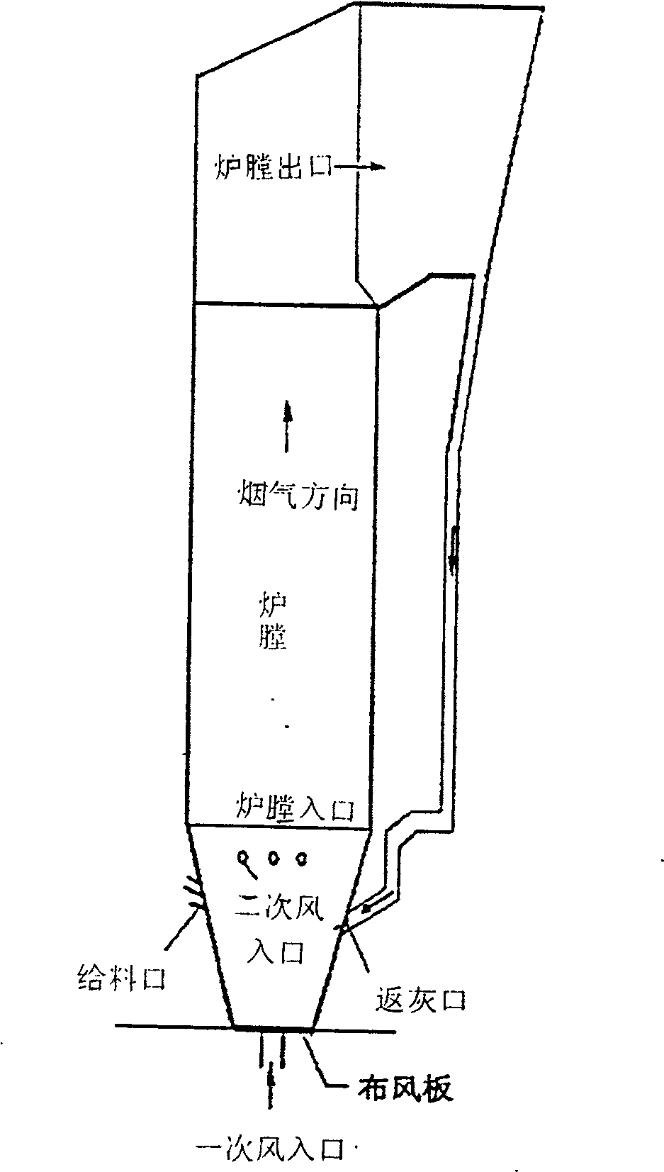
[0109] Example 2 The method of the present invention is applied to flow prediction in a circulating fluidized bed boiler of Wuhan Petrochemical Plant, which produces 75 tons of steam per hour, to assist in detecting faults. Such as image 3 As shown, the main section of the boiler furnace is 5.4×3.99m, the furnace height is about 22.5m, the average particle size of circulating ash particles in the furnace is 0.21mm, and the particle density is 2000kg / m. 3 , The furnace temperature is controlled at around 900℃, and the designed primary air volume is 49701Nm 3 / h, secondary air volume 33134Nm 3 / h. The main combustion reaction occurs in the furnace: C+O 2 →CO 2 . On the general platform provided by commercial CFD software, the drag coefficient calculated by the method of the present invention is written as an external interface program in a user-defined form to replace the method inside the software. When calculating, first perform a 1:1 geometric structure of the boiler furnace, an...

Embodiment 3

[0110] Example 3 The method of the present invention is applied to the prediction of flow field distribution in a new Sinopec oil refining multi-stage reactor to assist in optimization design. The diameter of the main section of the reactor is 3.4m, the inlet gas velocity is 15m / s, the inlet solid content is 1500t / h, the average particle size used is 0.075mm, and the particle density is 1300kg / m. 3 , The furnace operating temperature is about 400℃. The drag coefficient calculated by the method of the present invention is written as an external interface program to replace the internal method of the commercial software. When calculating, first perform a 1:1 geometric structure of the reactor, select the calculation method to be the two-fluid model under the double Euler coordinates; secondly set the temperature, and set the particle and gas properties according to the actual physical property system; the bottom surface gas The speed and solid speed are given according to the design...


PUM


Abstract

The invention discloses a method for measuring the distribution of flow parameters in a particle fluid two-phase flow reactor, which includes: calculating the conservation equation in each space microelement by a two-fluid model according to the structural size, physical properties and operating conditions of the reactor. Velocity and concentration distribution; calculate the combination of all variable roots satisfying the unsteady state equations of the global dynamics from the overall operating conditions of the reactor, and find the optimal root satisfying the extreme value condition to obtain the mesoscopic structural parameters; Solve the combination of all variable roots that satisfy the micro-local dynamic equations in a micro-element space, and find the optimal root that satisfies the extreme value condition; calculate the interphase drag force of the particle fluid, and replace the drag relationship of the two-fluid model for iterative calculation , to obtain the spatial distribution and time evolution of the concentration and velocity flow field in any micro-element of the reactor. The method of the invention can obtain the drag coefficient reflecting the actual situation, and can accurately calculate the processes of flow, reaction, heat transfer and mass transfer in the reactor.

Description

Technical field [0001] The invention relates to a particle fluid two-phase flow reactor, in particular to a method for measuring flow parameter distribution in a particle fluid two-phase flow reactor. Background technique [0002] The two-phase flow of granular fluid is widely present in process industry systems. With changes in physical properties and operating parameters, the two-phase flow exhibits complex structure and parameter distribution changes, which have direct effects on the pressure drop distribution, mass transfer, heat transfer efficiency, and reaction conversion rate in industrial reactors, sometimes even orders of magnitude. Impact. Therefore, how to accurately describe the flow structure and parameter distribution in the particle fluid two-phase flow reactor is an important task for the design, operation, control and amplification of the process industry. The method of predicting the interphase drag force of two-phase flow is one of the core contents to achieve ...

Claims


Application Information

Patent Timeline
Patent Type & Authority Patents(China)
IPC IPC(8): G01M10/00
Inventor 王维葛蔚杨宁李静海
Owner INST OF PROCESS ENG CHINESE ACAD OF SCI
Why Eureka
Try Eureka