Method for measuring flow parameter distribution in particle flow two-phase flow reactor
A technology for flow parameters and reactors, which is applied in fluid dynamics experiments, measuring devices, instruments, etc., can solve the problems of infeasibility of industrial reactors, difficult selection of sample space, and failure to consider the influence of cross-scale correlation on mesoscopic structure.
- Summary
- Abstract
- Description
- Claims
- Application Information
AI Technical Summary
Problems solved by technology
Method used
Image
Examples
Embodiment 1
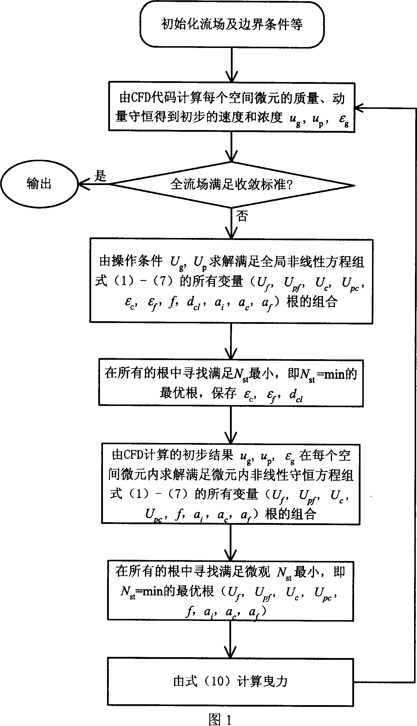
[0108] Example 1 The method of the present invention is applied to the flow prediction in a rapid fluidized calciner of coal series kaolin with an annual output of 1000 tons. Raw material kaolin average particle size 0.002mm, particle density 800kg / m 3 , The inner diameter of the calcination furnace is 0.45m, and the height of the furnace is 10.5m. The furnace temperature is controlled at around 900°C. The main reactions that take place are: C+O 2 →CO 2 , Al 2 o 3 2SiO2 2 ·H 2 O→Al 2 o 3 2SiO2 2 . During the calculation, on the general platform provided by commercial CFD software, the drag coefficient calculated by the method of the present invention according to the calculation block diagram is compiled into an interface program to replace the internal method of the software. First, the geometric structure of the reaction device is 1:1, and the calculation method is the two-fluid model under the double Euler coordinates; secondly, the temperature is set and the pro...
Embodiment 2
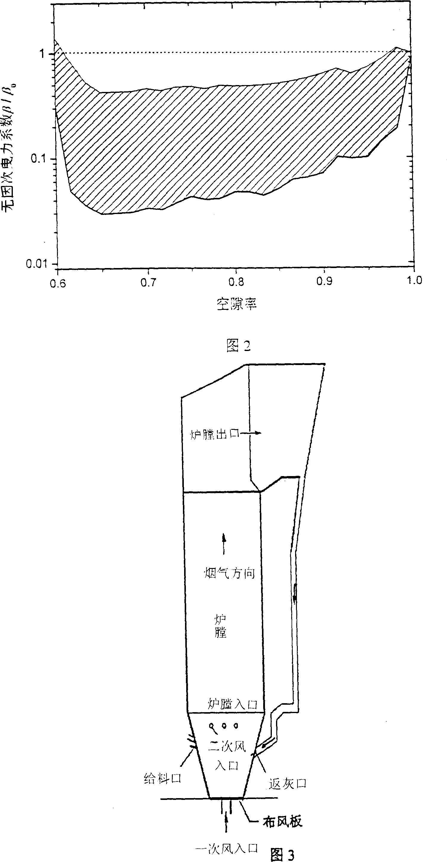
[0109] Example 2 The method of the present invention is applied to the flow prediction in the circulating fluidized bed boiler of Wuhan Petrochemical Plant, which produces 75 tons of steam per hour, to assist in the detection of faults. As shown in Figure 3, the main section of the boiler furnace is 5.4×3.99m, the height of the furnace is about 22.5m, the average particle size of circulating ash particles in the furnace is 0.21mm, and the particle density is 2000kg / m 3 , the furnace temperature is controlled at about 900°C, and the designed primary air volume is 49701Nm 3 / h, secondary air volume 33134Nm 3 / h. The combustion reaction mainly occurs in the furnace: C+O 2 →CO 2 . On the general platform provided by commercial CFD software, the drag coefficient calculated by the method of the present invention is written as an external interface program in a user-defined form to replace the internal method of the software. During the calculation, firstly, the geometric struct...
Embodiment 3
[0110] Example 3 The method of the present invention is applied to the prediction of the flow field distribution in the new refinery multi-stage reactor of Sinopec to assist in the optimization design. The diameter of the main section of the reactor is 3.4m, the inlet gas velocity is 15m / s, the inlet solid volume is 1500t / h, the average particle size of the particles used is 0.075mm, and the particle density is 1300kg / m 3 , The operating temperature of the furnace is about 400°C. The drag coefficient calculated by the method of the present invention is written as an external interface program to replace the internal method of the commercialized software. In the calculation, firstly, the geometric structure of the reactor is 1:1, and the calculation method is the two-fluid model under the double Euler coordinates; secondly, the temperature is set, and the properties of particles and gases are set according to the actual physical property system; the apparent gas at the bottom i...
PUM
 Abstract
Description
Claims
Application Information
 - R&D
- Intellectual Property
- Life Sciences
- Materials
- Tech Scout
- Unparalleled Data Quality
- Higher Quality Content
- 60% Fewer Hallucinations
Browse by: Latest US Patents, China's latest patents, Technical Efficacy Thesaurus, Application Domain, Technology Topic, Popular Technical Reports.
© 2025 PatSnap. All rights reserved.Legal|Privacy policy|Modern Slavery Act Transparency Statement|Sitemap|About US| Contact US: help@patsnap.com


