Drum-type quenching machine

A quenching machine and drum type technology, applied in quenching devices, heat treatment equipment, furnaces, etc., can solve the problems of reducing the contact probability between the quenching medium and the workpiece, restricting the turnover frequency, and wasting cold air medium.

Active Publication Date: 2009-08-26
ANHUI NINGGUO XINNING IND
View PDF5 Cites 0 Cited by
  • Summary
  • Abstract
  • Description
  • Claims
  • Application Information

AI Technical Summary

Problems solved by technology

[0002] The traditional quenching of casting balls and segmental workpieces has always used the wind quenching mechanical shaker, the stirring method of the oil quenching mechanical oil pool, supplemented by mist supply or air supply device, which is the second medium or called dual medium, single wind or mist quenching The methods are all limited by the process of air quenching mechanical shaker equipment, so there are many shortcomings after quenching the workpiece. For example, the hardness of the material workpiece after quenching is significantly reduced by 2-4HRC compared with oil quenching, and the hardness of the same batch of workpieces is uneven, with a difference of up to 7-8HRC, even the phenomenon of hardening impermeability, the surface of a single workpiece and the contrast between the hardness difference between the surface and the center is relatively large, because the mechanical shaker is to achieve the directional flip of the workpiece by swinging left and right up and down at a certain angle or by the speed difference of reciprocating operation, Therefore, the turning frequency and turning surface are restricted, and the shape and size of the workpiece are also greatly restricted. The location of the wind and water mist quenching medium can only be provided on the side or the top. During the quenching process, the workpiece facing the shaker can only be blown openly. It is impossible to form complete contact with the construction period parts at all, not only consumes a large amount of cold air medium, but also greatly reduces the contact probability between the quenching medium and the workpiece within a unit time, so that the phenomenon of incomplete quenching occurs, so the scope of application is also limited to a certain extent, and it is favored in the wear-resistant casting industry. Gradually eliminated. Compared with the air quenching mechanical shaker, the oil quenching method just makes up for its shortcomings. The workpieces of the same material can reach the ideal range after oil quenching. However, when the oil quenching process is used, the workpiece is completely immersed in the oil. In the medium, coupled with the super strong penetrating properties of the oil itself, it has high requirements on the quality of the quenched workpiece itself. Even if the workpiece itself has only a slight body defect, it will be enlarged during the quenching process, resulting in quenching cracks, quenching cracks or potential quenching microcracks. , Potential microcracks are the fatal hazard of workpiece products. Because they are not easy to detect, they are often mixed in the finished product. Therefore, the applicability of the oil quenching process is greatly limited at a certain stage. The oil quenching cooling cycle, as well as the disadvantages of large pollution and high investment have become the fetters of the industry

Method used


Image

  • Drum-type quenching machine

Examples


Embodiment Construction

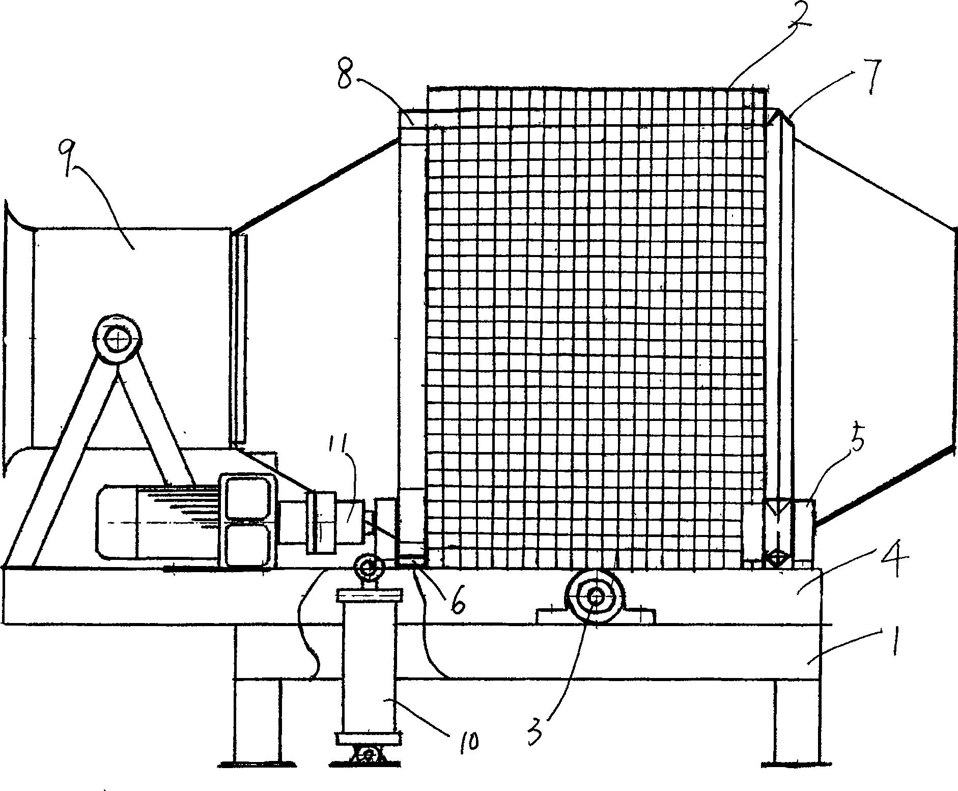
[0014] The drum type quenching machine includes a frame 1, a drum 2 with a grid wall, a drum bracket 4 is installed on the frame 1 through a rotating shaft 3, and a V-shaped support wheel group 5 is installed on the drum bracket 4 And the gear supporting wheel set 6, the V-shaped supporting wheel set 5 is at least composed of front and rear V-shaped supporting wheels, the gear supporting wheel set 6 is at least composed of front and rear gears, and the outer wall of the drum 2 is equipped with a V-shaped rim 7 and transmission ring gear 8, said drum V-shaped rim 7 is framed in the V-shaped supporting wheel set 5, and the transmission ring gear 8 is mounted on the gear supporting wheel set 6 and meshes with the front and rear gears. The inner wall of the drum 2 is fixed with a helical blade, and a V-shaped wheel cover is installed on the drum bracket 4 to be stuck outside the V-shaped rim 7 of the drum, and a jacking cylinder 10 is connected below one end of the drum bracket 4 ....


PUM

PropertyMeasurementUnit
diameteraaaaaaaaaa
lengthaaaaaaaaaa
diameteraaaaaaaaaa

Abstract

The invention discloses a drum type quenching machine, which includes a frame and a drum, and is characterized in that a drum bracket is installed on the frame through a rotating shaft, and a V-shaped support wheel group and a roller bracket are installed on the drum bracket. The gear support wheel set, the V-shaped support wheel set is at least composed of front and rear V-shaped support wheels, the gear support wheel set is composed of at least front and rear gears, and the outer wall of the drum is equipped with a V-shaped wheel ring and a transmission ring gear. The V-shaped rim frame of the drum is in the V-shaped support wheel group, the transmission ring gear frame is on the gear support wheels and meshes with each other, the inner wall of the drum is fixed with spiral blades, and the V-shaped support wheel is installed on the drum bracket. The shaped wheel sleeve is stuck outside the V-shaped wheel rim of the drum, and a jacking cylinder or an oil cylinder is connected below one end of the drum bracket. The drum quenching machine can meet the various indicators and process requirements of the current casting ball quenching treatment. It has been successfully applied in the wear-resistant casting ball industry. The hardness of the casting after quenching is uniform, reaching the index of oil quenching, and the hardness of batch processing is uniform. The performance is higher than that of oil quenching, and the occurrence of quenching cracks is completely avoided.

Description

technical field [0001] The invention relates to a metal heat treatment equipment. It is mainly used for quenching treatment equipment of grinding media wear-resistant casting balls and segments of powder engineering. Background technique [0002] The traditional quenching of casting balls and segmental workpieces has always used the wind quenching mechanical shaker, the stirring method of the oil quenching mechanical oil pool, supplemented by mist supply or air supply device, which is the second medium or called dual medium, single wind or mist quenching The methods are all limited by the process of air quenching mechanical shaker equipment, so there are many shortcomings after quenching the workpiece. For example, the hardness of the material workpiece after quenching is significantly reduced by 2-4HRC compared with oil quenching, and the hardness of the same batch of workpieces is uneven, with a difference of up to 7-8HRC, even the phenomenon of hardening impermeability, ...

Claims


Application Information

Patent Timeline
Patent Type & Authority Patents(China)
IPC IPC(8): C21D1/62C21D9/00
Inventor 周道宏
Owner ANHUI NINGGUO XINNING IND
Why Eureka
Try Eureka