
High-efficiency quenching device for large-diameter rollers

A quenching device and large-diameter technology, applied in the direction of quenching device, furnace, furnace type, etc., can solve the problems of large heat input, insufficient quenching, high temperature, etc.

Active Publication Date: 2022-04-12
浙江久恒光电科技有限公司
View PDF18 Cites 0 Cited by
  • Summary
  • Abstract
  • Description
  • Claims
  • Application Information

AI Technical Summary

Problems solved by technology

For the power in motion, it can be achieved by reducing the laser scanning speed or widening the width of the laser spot in the direction of parallel movement, but reducing the laser scanning speed will reduce the overall quenching efficiency, while the width of the laser spot in the direction of parallel movement increases, the laser The area of ​​the spot becomes larger. When the required quenching power density is constant, it is necessary to use a higher power laser. For such a roller with a large diameter, multiple parallel lasers can be used for quenching at the same time to improve the quenching efficiency. efficiency
The second is the rapid cooling process. Due to the low carbon content of low-carbon steel, the C curve is seriously shifted to the left. After the material leaves the laser irradiation area, there must be a fast enough cooling rate to make the material within the depth of the layer better. Quenching hardness. In the previous step, in order to improve the efficiency and ensure the depth of the layer, multiple high-power lasers were used. The overall heat input is very large. In the case of constant heat capacity of the material, it can be cooled by air cooling, thermal radiation air cooling or even simple water cooling. Neither can conduct a large amount of excess heat away, resulting in higher and higher temperature of the substrate, unable to achieve rapid cooling, and also fail to achieve the purpose of quenching

Method used


Image

  • High-efficiency quenching device for large-diameter rollers
  • High-efficiency quenching device for large-diameter rollers
  • High-efficiency quenching device for large-diameter rollers

Examples


Embodiment Construction

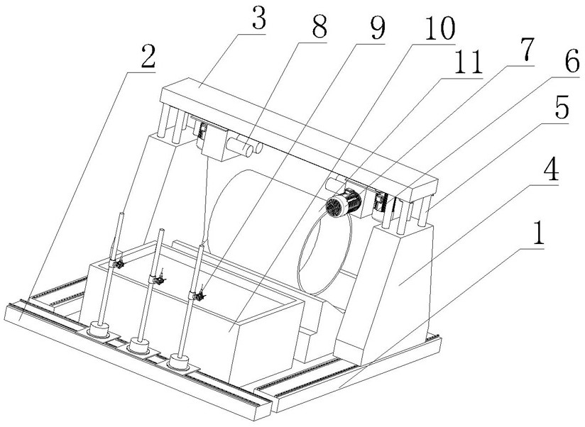
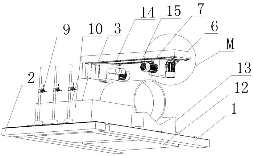
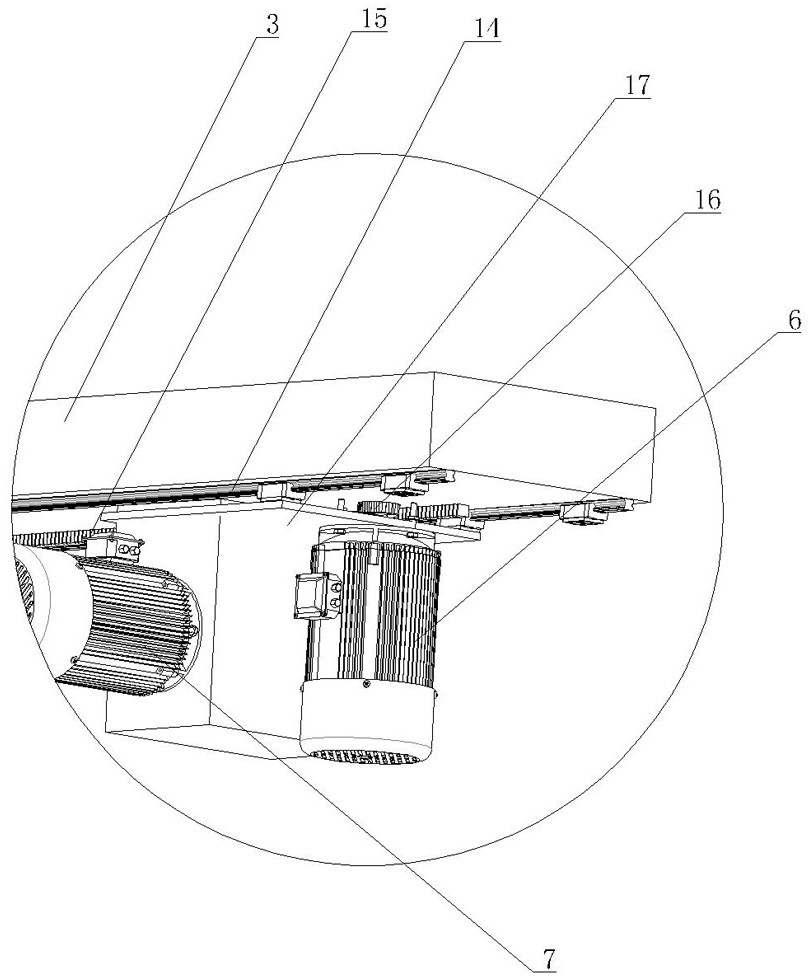
[0016] Referring to the accompanying drawings, this high-efficiency quenching device for large-diameter rollers includes a ground-rail gantry, a laser head 9, and a cooling pool 10. The ground-rail gantry includes a beam 3, two parallel Y-axis guide rails 1, and The column 4 is movable on two parallel Y-axis guide rails 2, the beam 3 is liftably mounted on the two movable columns 4, and the laser head 9 is movably installed on the X-axis guide rail 2 , at least two laser heads 9 are installed on the X-axis guide rail 2; in this embodiment, three laser heads 9 are respectively connected to three 6000W power lasers through optical fibers, and the quenching efficiency can reach 3-6m 2 / H, the laser heads 9 are installed side by side on the X-axis guide rail 2. As for how the laser head 9 moves on the X-axis guide rail, it is moved by gear transmission, which belongs to common knowledge and will not be repeated. The movement of the column 4 on the Y-axis guide rail can be promoted...


PUM


Abstract

The invention discloses a high-efficiency quenching device for large-diameter rollers, which is characterized in that it includes a ground-rail type gantry frame, a laser head (9), and a cooling water pool (10). The ground-rail type gantry frame includes a beam (3), two Parallel Y-axis guide rails (1), and movable uprights (4) on the two parallel Y-axis guide rails (1), the crossbeam can be erected on the two movable uprights (4) , the laser head (9) is movably installed on the X-axis guide rail (2), the two ends of the beam (3) are equipped with rotatable and axially movable support rods (8), the cooling water pool (10) Place it in the frame formed by the X-axis guide rail (2) and two Y-axis guide rails (1). The quenching device with this structure can conveniently quench large-diameter rollers, has a simple structure and is convenient to use, and can be widely used in quenching rollers with larger diameters.

Description

technical field [0001] The invention relates to a quenching device, in particular to a high-efficiency quenching device for large-diameter rollers. Background technique [0002] Large diameter rollers are commonly used on road rollers. Such large-diameter rollers are generally made of low-carbon steel in order to meet their mechanical and welding properties. Low-carbon steel itself has poor wear resistance, and the road surface conditions are complex during road roller construction, and the wheels are required to have strong wear resistance. Traditionally, the quenching process is used to improve the hardness and wear resistance of the material. The wheel body of the large-diameter roller is too large, and there is no suitable heat treatment furnace. Therefore, someone invented a hardening process for the surface of low-carbon steel to effectively solve the problem of low-carbon steel. The problem that the quenching hardness is not high enough. Check the Chinese patent dat...

Claims


Application Information

Patent Timeline
Patent Type & Authority Patents(China)
IPC IPC(8): C21D1/63C21D1/09C21D9/34
CPCC21D1/63C21D1/09C21D9/34
Inventor 吴旭浩高炳奖徐乐
Owner 浙江久恒光电科技有限公司
Learn More