
Inverter

A technology for inverter devices and industrial machines, applied in the direction of converting irreversible DC power input into AC power output, etc., can solve problems such as stop operation, cannot continue, need time and energy, and achieve the effect of preventing operation stop

Active Publication Date: 2009-11-04
FUJI ELECTRIC CO LTD
View PDF4 Cites 0 Cited by
  • Summary
  • Abstract
  • Description
  • Claims
  • Application Information

AI Technical Summary

Problems solved by technology

This creates a problem: the inverter will stop and subsequent operations will not continue
Another problem, however, is that this monitoring takes time and effort

Method used


Image

  • Inverter
  • Inverter
  • Inverter

Examples


Embodiment Construction

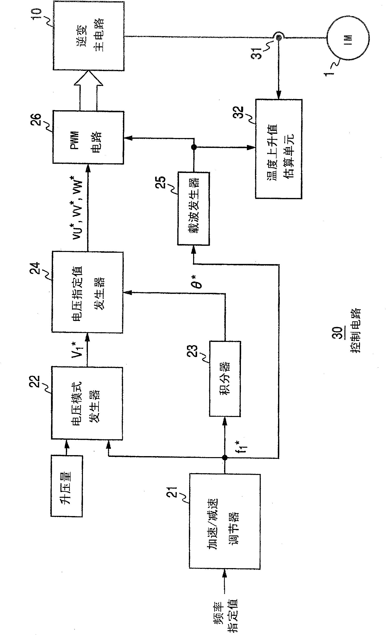
[0019] figure 1 is a circuit diagram of an inverter device according to an embodiment of the present invention. have with image 3 Elements of the same function in the conventional circuit shown are labeled with the same reference numerals and will not be described in detail again.

[0020] figure 1 The inverter device shown has a control circuit 30, which passes through the image 3 A current detector 31 and a temperature rise estimation unit 32 are additionally provided in the control circuit 20 to form.

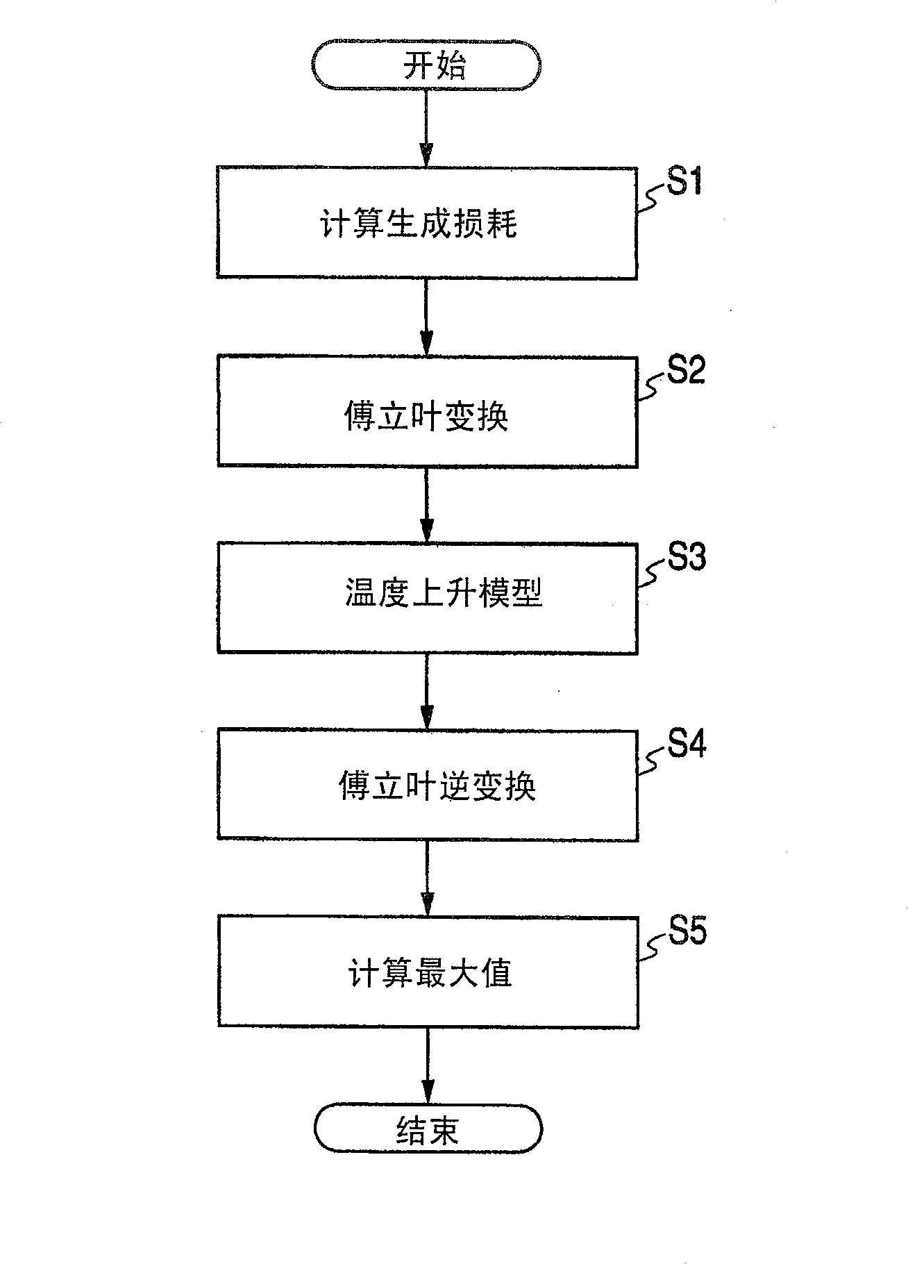
[0021] will be referred to below figure 2 Flowchart description of figure 1 The operation of the temperature rise value estimating unit 32 is shown.

[0022] use figure 1 The temperature rise value estimating unit 32 of the inverter device is shown, and the operating mode of one cycle in the industrial machine is observed by the inverter device, and the inverter circuit 13 that constitutes the inverter main circuit 10 is derived based on the observation data (see...


PUM


Abstract

An operation pattern of one cycle in a preset industrial machine is observed by a current detector and a temperature rise value estimating unit additionally provided in a conventional inverter device. The temperature rise value estimating unit derives a maximum temperature rise estimated value of each component when the operation pattern is periodically repeated based on observed values ​​for one cycle and temperature rise patterns of the respective constituent components of the inverter device.

Description

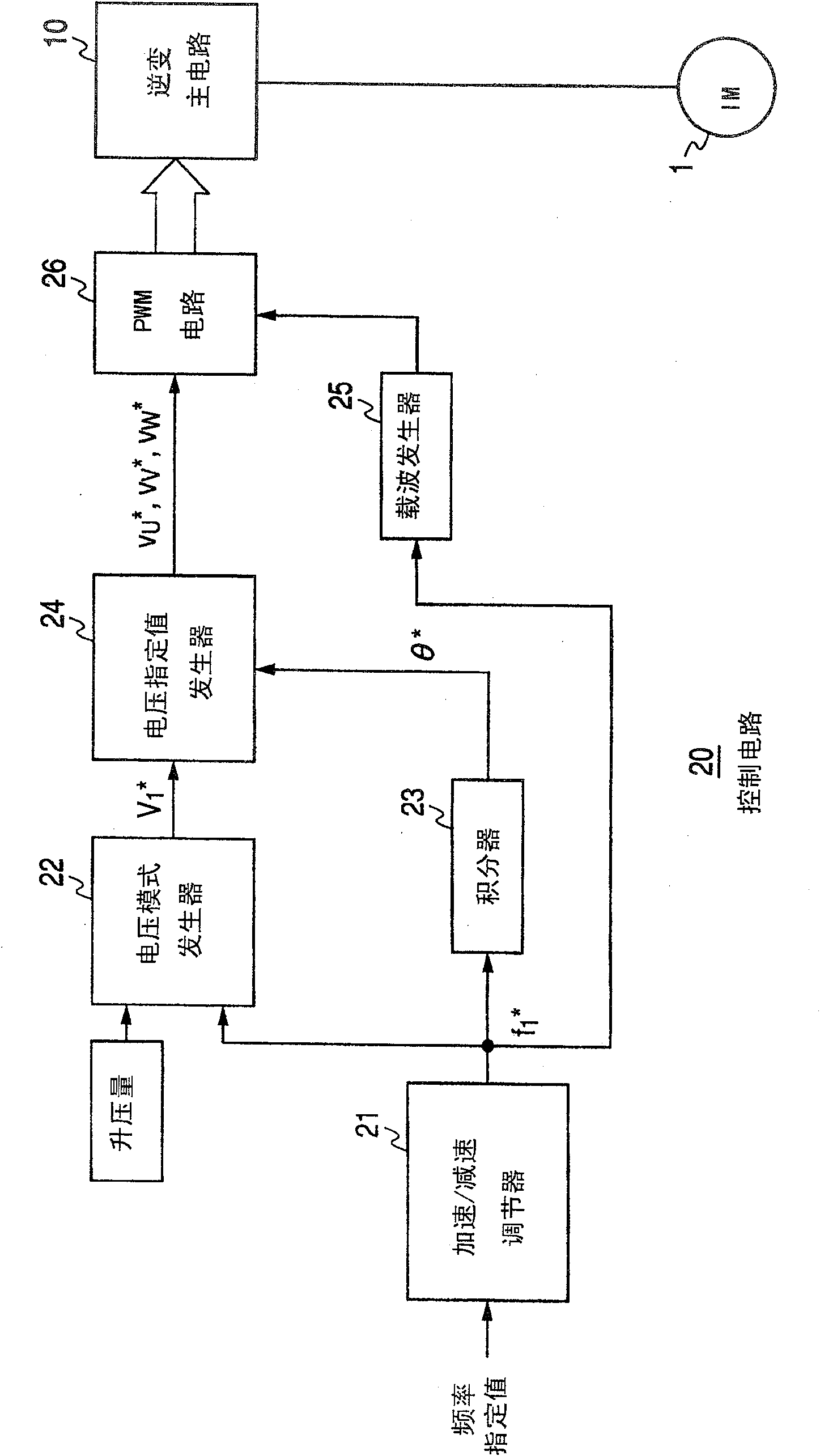
technical field [0001] More particularly, the present invention relates to an inverter device that drives an AC motor as a mechanical power source for various types of industrial machines performing repetitive operations in preset operation modes. Background technique [0002] image 3 is a circuit diagram showing an exemplary conventional inverter device of this type called a V / f control inverter. [0003] exist image 3 Among them, 10 means that it has the Figure 4 The inverter main circuit of the configuration is shown, and 20 denotes a control circuit that performs control to supply desired AC power from the inverter main circuit 10 to the AC motor 1 . The control circuit 20 includes an acceleration / deceleration regulator 21 for increasing or decreasing a frequency specified value from a high-level controller (not shown) with a desired gradient for controlling the running operation of the industrial machine and finally switching it into a frequency setting value f con...

Claims


Application Information

Patent Timeline
Patent Type & Authority Patents(China)
IPC IPC(8): H02M7/42H02M7/54
Inventor 市原孝男
Owner FUJI ELECTRIC CO LTD
Learn More