Aerospace sequential deployment mechanism
A technology for deploying mechanisms and aerospace space, applied in space navigation equipment, space navigation equipment, space navigation vehicles, etc., can solve the problems of uncontrollable deployment sequence, deployment speed, large impact force and vibration, etc., and achieve simplified power source , small shock and vibration, energy-saving effect
- Summary
- Abstract
- Description
- Claims
- Application Information
AI Technical Summary
Problems solved by technology
Method used
Image
Examples
specific Embodiment approach 1
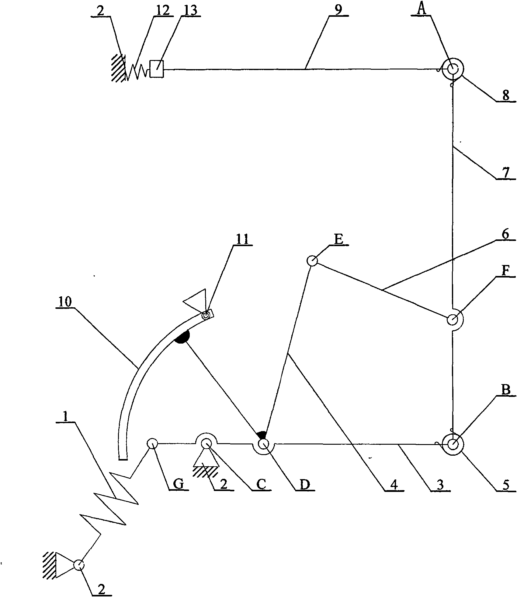
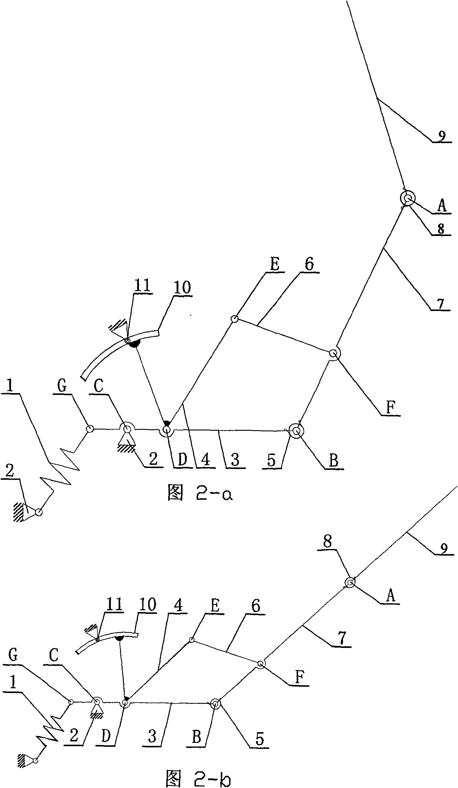
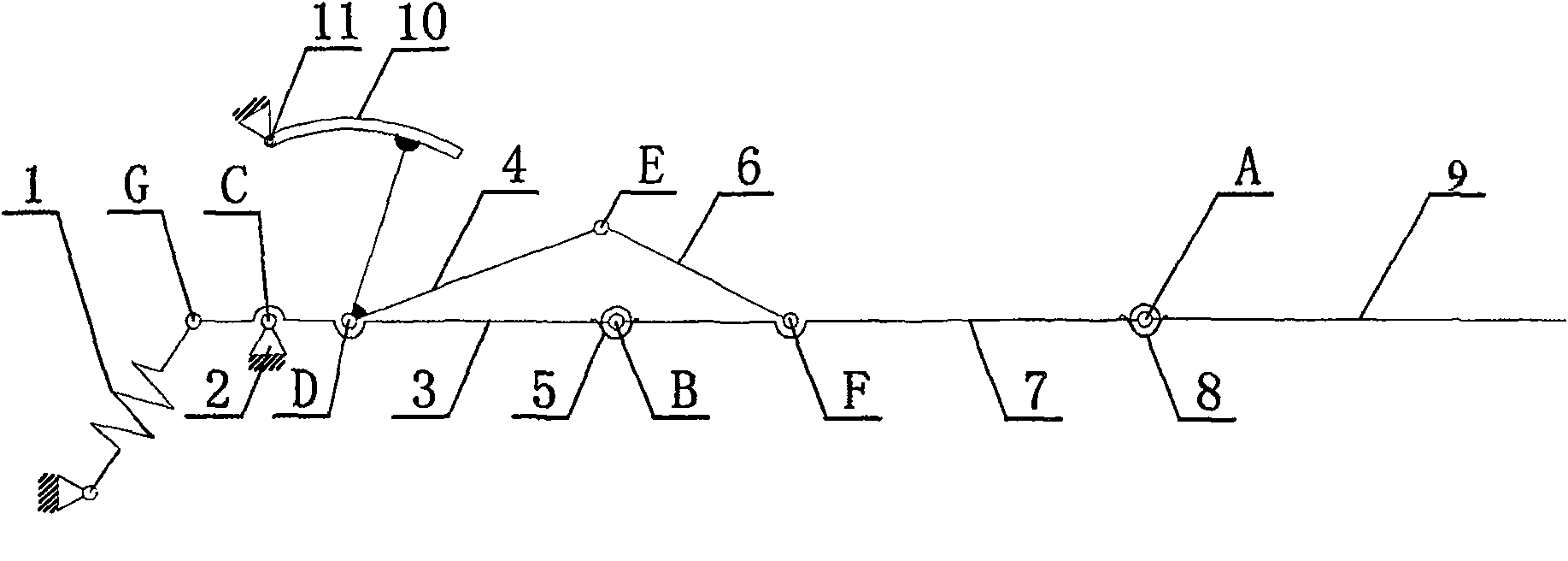
[0007] Specific implementation mode one: combine figure 1 , Figure 2-a~Figure 2-d Describe this embodiment, the aerospace space sequence deployment mechanism of this embodiment is comprised of spring damper 1, space mechanism frame 2, first member 3, bent shape connecting rod 4, first driving part 5, first connecting rod 6, The second component 7, the second driving part 8, the third component 9, the arc pull rod 10, the roller 11, the thruster 12, and the pyrotechnic cutting device 13 are composed; One end is connected, and the other end of pyrotechnic cutting device 13 is connected with space mechanism frame 2 by thruster 12, and at this moment, aerospace space sequential deployment mechanism is in locked state, and the other end of third component 9 and one end of second component 7 Hinged at the first hinge point A, the second driving part 8 is arranged at the first hinge point A of the third member 9 and the second member 7, and provides a driving torque for the expansi...
specific Embodiment approach 2
[0008] Specific implementation mode two: combination figure 1 , Figure 4 To illustrate this embodiment, the first driving part 5 of this embodiment is composed of a first elastic driving part 5-1 and a first harmonic reducer; the first harmonic reducer is composed of a first harmonic reducer wave generator 5-2. The first harmonic reducer short-cup flexible wheel 5-3, the first harmonic reducer rigid wheel 5-4; the first elastic driving part 5-1 and the first harmonic reducer wave generator The device 5-2 is coaxial, one end of the first elastic driving part 5-1 is fixedly connected to the first member 3, and the other end of the first elastic driving part 5-1 is connected to the first harmonic reducer wave generator 5-2 The first harmonic reducer wave generator 5-2 is driven to rotate around its own axis by using the energy stored in the first elastic drive part 5-1, and the rigid wheel 5-4 of the first harmonic reducer is fixed to the first member 3 Then, the first harmoni...
specific Embodiment approach 3
[0009] Specific implementation mode three: combination figure 1 , image 3 To illustrate this embodiment, the second driving part 8 of this embodiment is composed of a second elastic driving part 8-1 and a second harmonic reducer; the second harmonic reducer is composed of a second harmonic reducer wave generator 8-2. The second harmonic reducer short-cup flexible wheel 8-3, the second harmonic reducer rigid wheel 8-4; the second elastic driving part 8-1 and the second harmonic reducer wave generator The device 8-2 is coaxial, one end of the second elastic driving part 8-1 is fixedly connected to the second member 7, and the other end of the second elastic driving part 8-1 is connected to the wave generator 8-2 of the second harmonic reducer The second harmonic reducer wave generator 8-2 rotates around its own axis by using the energy stored in the second elastic drive part 8-1, and the second harmonic reducer rigid wheel 8-4 is fixed to the second member 7 Then, the second ...
PUM
 Abstract
Description
Claims
Application Information
 - R&D
- Intellectual Property
- Life Sciences
- Materials
- Tech Scout
- Unparalleled Data Quality
- Higher Quality Content
- 60% Fewer Hallucinations
Browse by: Latest US Patents, China's latest patents, Technical Efficacy Thesaurus, Application Domain, Technology Topic, Popular Technical Reports.
© 2025 PatSnap. All rights reserved.Legal|Privacy policy|Modern Slavery Act Transparency Statement|Sitemap|About US| Contact US: help@patsnap.com


