Component with a weld projection having a projection and lamp housing part comprising a component with a weld projection

A technology for bulges and lamp housings, applied in welding/welding/cutting articles, welding equipment, laser welding equipment, etc., can solve zinc coating evaporation, holes, sand holes and spatters in the connection area, failure to form welding connections, etc. question

Inactive Publication Date: 2010-02-24
PATENT TREUHAND GESELLSCHAFT FUER ELECTRIC GLUEHLAMPEN M B H
View PDF6 Cites 0 Cited by
  • Summary
  • Abstract
  • Description
  • Claims
  • Application Information

AI Technical Summary

Problems solved by technology

[0004] The disadvantage of this welded connection is that the zinc coating of the housing parts vaporizes explosively during welding, resulting in holes, blisters and spatter in the connection area
A further disadvantage is that the heat generated during welding leads to a reaction of the housing parts and the plastic shell, so that the quality of the welded connection is greatly reduced or the welded connection cannot be formed

Method used


Image

  • Component with a weld projection having a projection and lamp housing part comprising a component with a weld projection
  • Component with a weld projection having a projection and lamp housing part comprising a component with a weld projection

Examples


Embodiment Construction

[0023] The invention will be illustrated below with the aid of welding projections for welding zinc-coated shielding housing parts. As already mentioned, the welding projections according to the invention are not limited to such housing parts only.

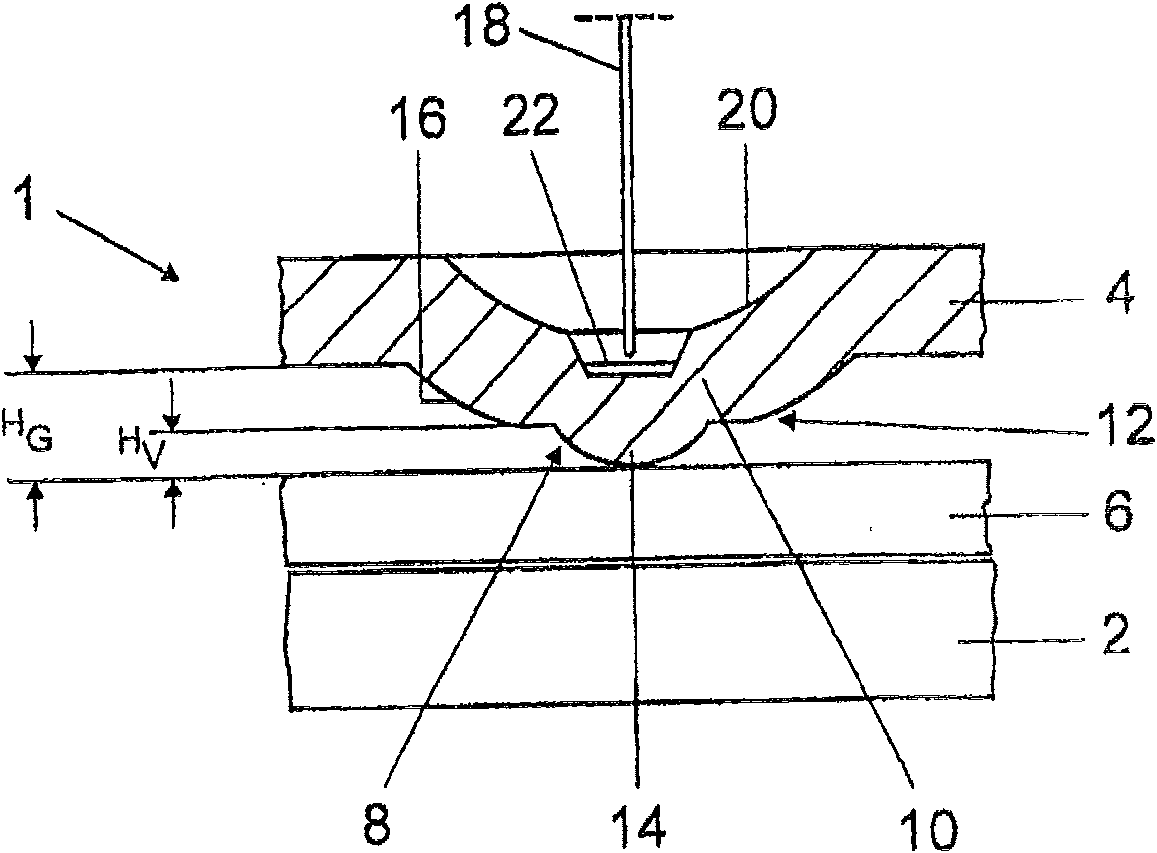
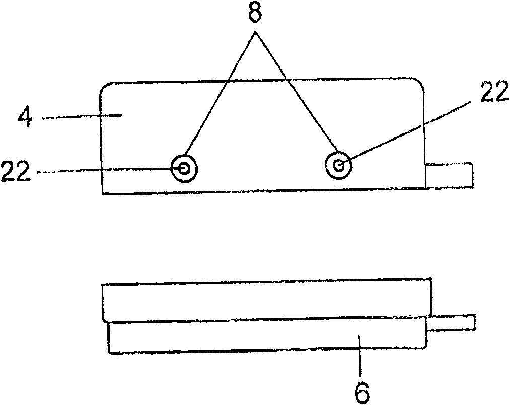
[0024] figure 2 A schematic illustration of a two-part, substantially cuboid shielding housing which surrounds the plastic lampholder 2 is shown. The upper part 4 of the shielding housing is provided on its top face with an opening (not shown) for the discharge chamber of the high-pressure discharge lamp. The lower part 6 overlaps the upper part 4 , so that in the area of ​​the overlap the outer wall of the lower part 6 bears against the inner wall of the upper part 4 in the region of the welding bead 8 . Details of high-pressure discharge lamps are described, for example, in WO 00 / 59269. The shielding housing 1 has two housing parts 4, 6 made of galvanized sheet steel, which in their figure 1 A plurality of welding bumps 8 a...


PUM

PropertyMeasurementUnit
heightaaaaaaaaaa

Abstract

The invention relates to a first component which comprises a weld projection (8), especially for laser welding, having an indent (10) that is disposed in a first component (4) and that can be welded together with at least one second component (6). The invention is characterized in that the weld projection (8) has a projection (14) and can be brought into contact with the second component (6) via said projection. The invention also relates to a shielding housing (1) comprising such a weld projection (8) for a lamp base.

Description

technical field [0001] The invention relates to a metal lamp housing part. Background technique [0002] In principle, the solder bumps according to the invention can be used in many different soldering methods. However, the main field of application of the welding projections lies in laser welding methods, in particular for welding zinc-coated shielding housing parts of lamps. [0003] It is known from the prior art to use shielding housings made of galvanized sheet steel in order to improve electromagnetic compatibility (EMV), for example of discharge lamps. Such a shielding housing consists of two housing parts which surround the plastic base of the lamp and which are connected together by means of overlapping welds. One of the housing parts is provided with a plurality of approximately semicircular welding projections in the welding region and can be brought into contact with the second housing part via these welding projections. The two housing parts are then joined ...

Claims


Application Information

Patent Timeline
Patent Type & Authority Patents(China)
IPC IPC(8): B23K26/24B23K26/32B23K33/00H05B41/02H01R33/06B23K101/34B23K101/36B23K103/04
CPCB23K26/246B23K33/00B23K2203/04B23K2201/34B23K2201/36B23K26/3293B23K26/3206B23K26/32B23K26/244B23K2101/34B23K2101/36B23K2103/04B23K2103/08B23K2103/50
Inventor B·米特勒T·施米特-莱曼
Owner PATENT TREUHAND GESELLSCHAFT FUER ELECTRIC GLUEHLAMPEN M B H
Why Eureka
Try Eureka