Concentrated brine high dispersion dehydration equipment

A dehydration equipment and highly dispersed technology, applied in the direction of spray evaporation, etc., can solve the problems of affecting efficiency, waste of resources, insufficient steam pressure, etc., and achieve the effects of improving dehydration efficiency, improving recycling, and accelerating evaporation speed

Active Publication Date: 2018-10-16
连云港中星能源有限公司
View PDF6 Cites 0 Cited by
  • Summary
  • Abstract
  • Description
  • Claims
  • Application Information

AI Technical Summary

Problems solved by technology

[0003] At present, the commonly used concentrated brine treatment processes include multi-effect evaporation, electrodialysis and reverse osmosis, etc. These treatment processes not only have the disadvantages of large equipment investment, high treatment cost and poor economy, but also the high-concentration brine produced cannot be effectively disposed of. The use of direct evaporation not only causes high energy consumption, but also is easy to scale, resulting in waste of resources and other shortcomings
[0004] In the prior art, the high-dispersion method is used to treat the concentrated brine, and the solution is highly dispersed through the high-dispersion equipment, so that the solution forms extremely fine liquid particles of different sizes and forms a highly dispersed mist with the gas. The lower the ratio, the water vapor is more likely to overflow, and the concentration of concentrated brine is reduced to achieve the treatment of industrial wastewater, but the following problems exist in the prior art: high dispersion is a heat-absorbing process, such as the temperature of the high dispersion chamber is not high enough , leading to insufficient vapor pressure of the liquid, so that a large amount of water vapor cannot be formed, which affects the efficiency of liquid dispersion into water vapor, and then the dehydration efficiency of concentrated brine decreases, and the effect of concentrating concentrated brine is poor

Method used


Image

  • Concentrated brine high dispersion dehydration equipment

Examples


Embodiment Construction

[0017] The present invention will be described in further detail below by means of specific embodiments:

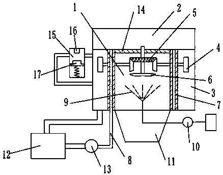
[0018] The reference signs in the accompanying drawings of the description include: high dispersion chamber 1, steam chamber 2, condensation chamber 3, turbine 4, bevel gear 5, negative pressure blade 6, heating insulation cover 7, steam pipe 8, high dispersion net 9, high pressure Water pump 10, concentration chamber 11, water storage tank 12, steam pump 13, mesh gas distributor 14, control box 15, switch 16, piston 17.

[0019] The embodiment is basically as attached figure 1 Shown: a high dispersion dehydration equipment for concentrated brine, including a high dispersion chamber 1, a steam chamber 2, a concentration chamber 11 and a condensation chamber 3, the concentration chamber 11 is located under the high dispersion chamber 1, and the condensation chamber 3 is located on the two sides of the high dispersion chamber 1 On the side, the high dispersion chamber 1 is...


PUM


Abstract

The invention belongs to the field of industrial wastewater treatment equipment and in particular discloses strong brine high dispersion and dehydration equipment. According to the equipment, a turbine is arranged in a condensing chamber; a bevel gear is arranged in a high dispersion chamber; a rotating shaft is arranged on the bevel gear; a plurality of negative pressure blades are arranged on the rotating shaft; a steam pipe is arranged in a heating insulation jacket; a gas guide pipe is arranged on one side of the condensing chamber; a control box is arranged on the gas guide pipe; a spring is arranged at the bottom in the control box; a piston is arranged on the spring; a piston-contactable switch is arranged on the top of the control box; a water storage tank is arranged below the condensing chamber and connected with the condensing chamber through a water inlet pipe; a drainage pipe is arranged on one side of the water storage tank; a steam pump is arranged on the drainage pipe and electrically connected with the switch; one end of the steam pump is connected with the steam pipe. According to the strong brine high dispersion and dehydration equipment provided by the scheme, a high dispersion chamber is kept at a high temperature.

Description

technical field [0001] The invention relates to the field of industrial wastewater treatment equipment. Background technique [0002] In the production process of chemical, electric power, petroleum, pharmaceutical and metallurgical industries, a large amount of concentrated brine is discharged, mainly including reverse osmosis concentrated brine, circulating cooling system sewage and boiler sewage. This type of wastewater contains a large amount of dissolved inorganic salts , the salinity can be as high as tens of grams per liter. If such wastewater is directly discharged into the receiving water body (river, river, lake or sea, etc.), it will break the balance of the receiving water body and cause serious damage to the biological environment in the receiving water body. Destruction threatens the survival of animals and plants in the water. [0003] At present, the commonly used concentrated brine treatment processes include multi-effect evaporation, electrodialysis and re...

Claims


Application Information

Patent Timeline
Patent Type & Authority Patents(China)
IPC IPC(8): B01D1/20
CPCB01D1/20
Inventor 袁世菊
Owner 连云港中星能源有限公司
Why Eureka
Try Eureka