Mounting system for flat panel electronic display

An electronic display and display technology, which is applied to the parts of the instrument, instruments, identification devices, etc., can solve the problem of loosening of the friction adjustment mechanism

Inactive Publication Date: 2007-10-03
CSAV
View PDF3 Cites 6 Cited by
  • Summary
  • Abstract
  • Description
  • Claims
  • Application Information

AI Technical Summary

Problems solved by technology

However, a disadvantage of previous friction adjustment mechanisms is that friction adjustment mechanisms tend to require a great deal of effort to adjust
Another disadvantage is that the friction adjustment mechanism tends to loosen over time due to the weight of the monitor

Method used


Image

  • Mounting system for flat panel electronic display
  • Mounting system for flat panel electronic display
  • Mounting system for flat panel electronic display

Examples


Embodiment Construction

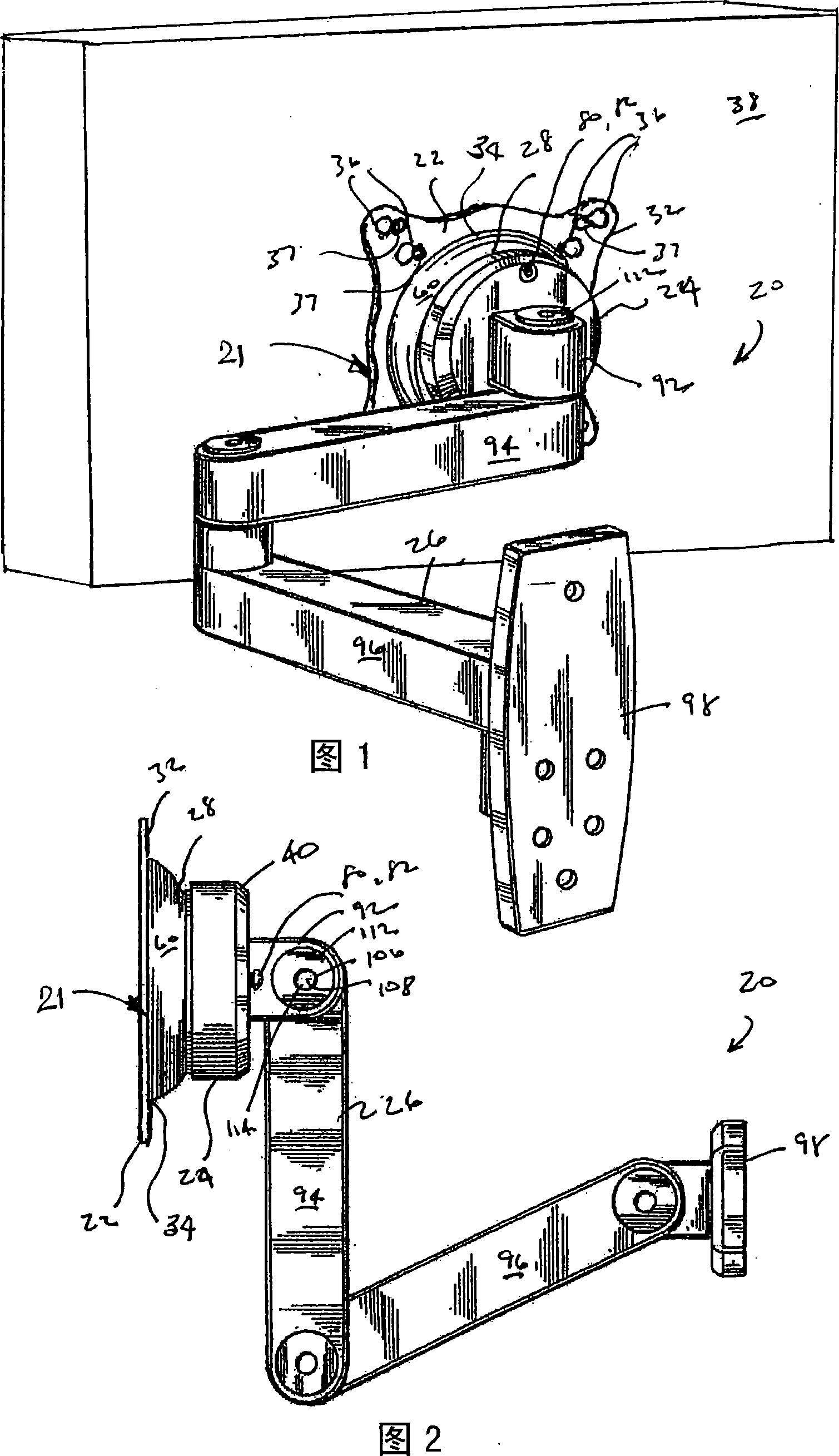
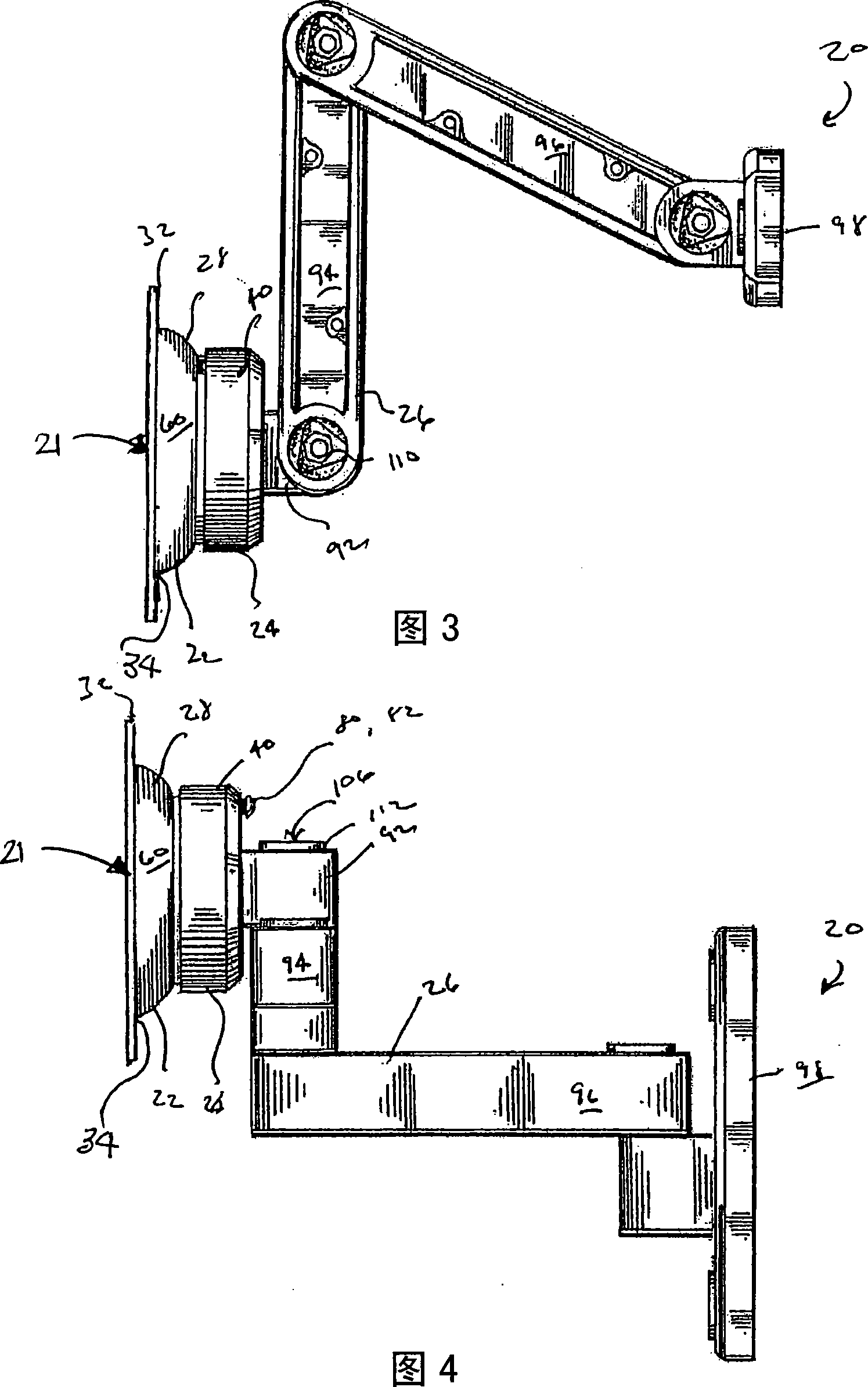
[0035] A mounting device is generally indicated at 20 in the drawings and generally includes a mounting device assembly 21 having a display interface 22 , a guide structure 24 and a support structure 26 in accordance with one embodiment of the present invention.

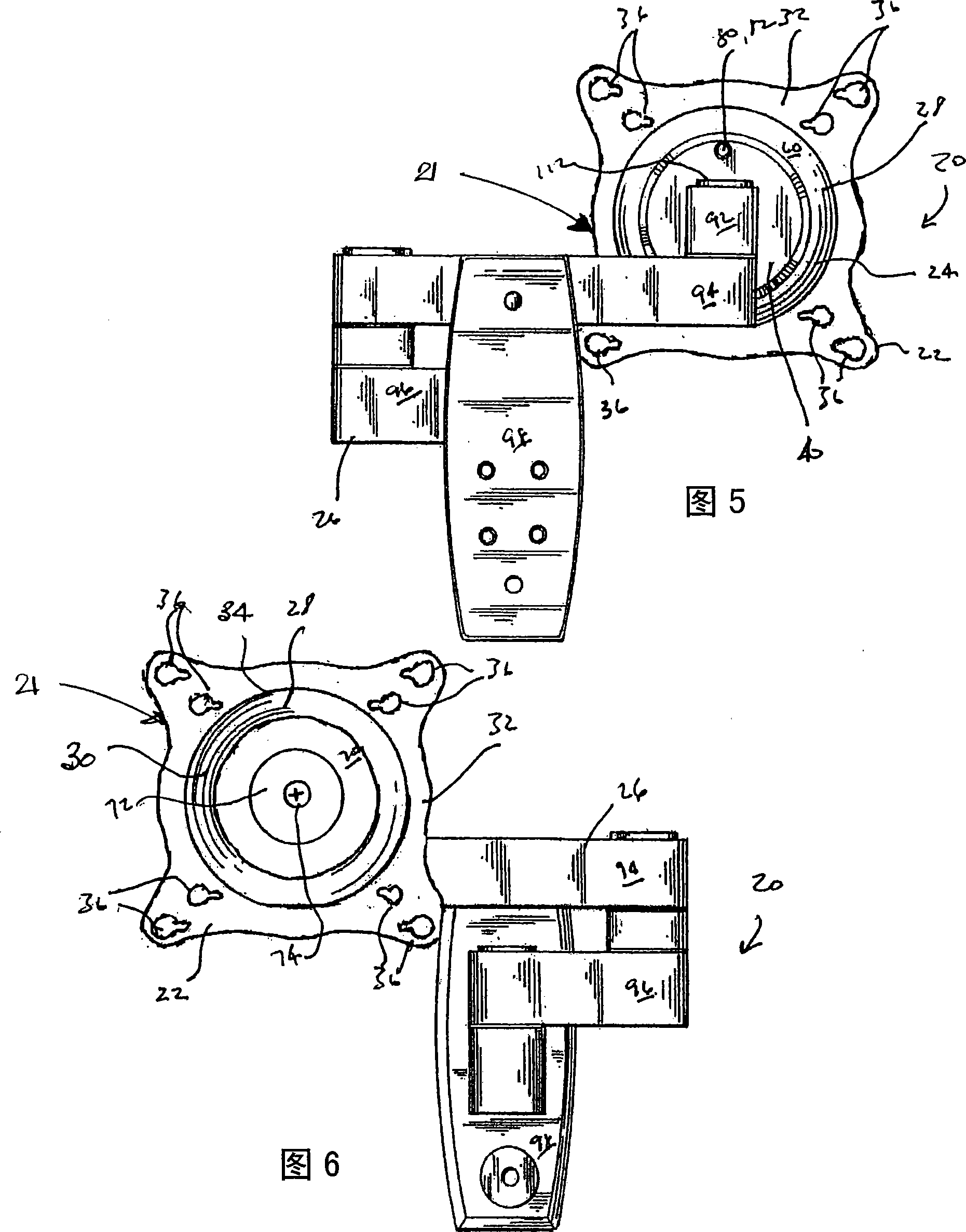
[0036] Referring to FIGS. 1-10 , the display interface 22 of the mounting device 20 generally includes a truncated spherical cup 28 defining an opening 30 . Flange portion 32 extends laterally outwardly from an outer edge 34 of truncated spherical cup 28 and includes an aperture 36 defined therein for receiving a fastener 37 (see FIG. 1 ) to secure display interface 22 on the electronic display device 38 . The cup wall 33 of the frusto-spherical cup 28 terminates at a rear wall 35 . The rear wall 35 has a central aperture 39 defined therein.

[0037] The guide structure 24 of the mounting device 20 generally includes a body portion 40 , an outer bearing 42 and an inner bearing assembly 44 . Body portion 40 is gene...


PUM


Abstract

A flat panel electronic display mount includes a display mount assembly having a discontinuous bearing, the bearing being expandable radially responsive to an increased frictional biasing force, the biasing force being applied axially to the discontinuous bearing, the radial expandability assisting in maintaining a desired amount of frictional engagement afforded by the discontinuous bearing. A flat panel electronic display mount further includes a display mount assembly having a bearing, the bearing having a central axis, a biasing means being selectively engagable with the bearing. Additionally, in a flat panel electronic display mount, a method of maintaining a desired amount of frictional engagement.

Description

[0001] related application [0002] This application claims the benefit of US Provisional Patent Application Serial No. 60 / 756,181, filed January 4, 2006, which is hereby incorporated by reference in its entirety. technical field [0003] This invention relates to mounts for electronic displays, and more particularly to devices for mounting flat panel electronic displays, such as plasma and LCD screens, to fixed structures. Background technique [0004] Flat panel displays are becoming more and more popular replacing projection devices and CRTs. Flat panel displays are typically mounted on a structure such as a wall. Flat panel displays, especially LCDs, are typically best viewed from a position directly in front of the display. Displayed images are often too dark or not visible at all if viewed from an obvious angle. [0005] Therefore, it is preferable that the angle of the flat panel display can be adjusted for optimum viewing. Various prior art positioning devices ha...

Claims


Application Information

Patent Timeline
Patent Type & Authority Applications(China)
IPC IPC(8): G12B9/08G12B5/00G09F9/00F16M11/00
CPCF16M11/14F16M11/02F16M11/04F16M11/105F16M11/12F16M11/2014F16M13/02F16M2200/068G06F1/1601
Inventor 吉姆·沃尔福特乔尔·菲斯特多米尼克·格雷尼克·施塔内克
Owner CSAV
Why Eureka
Try Eureka