Defroster duct

A technology of defroster and duct, which is applied in the direction of vehicle cleaning, heating/cooling equipment, vehicle maintenance, etc. It can solve the problems of local unevenness and achieve the effect of uniform blowing distribution

Inactive Publication Date: 2007-11-21
CALSONIC KANSEI CORP
View PDF1 Cites 7 Cited by
  • Summary
  • Abstract
  • Description
  • Claims
  • Application Information

AI Technical Summary

Problems solved by technology

Therefore, although the blowing distribution is wide, it may be locally uneven

Method used


Image

  • Defroster duct
  • Defroster duct
  • Defroster duct

Examples


Embodiment Construction

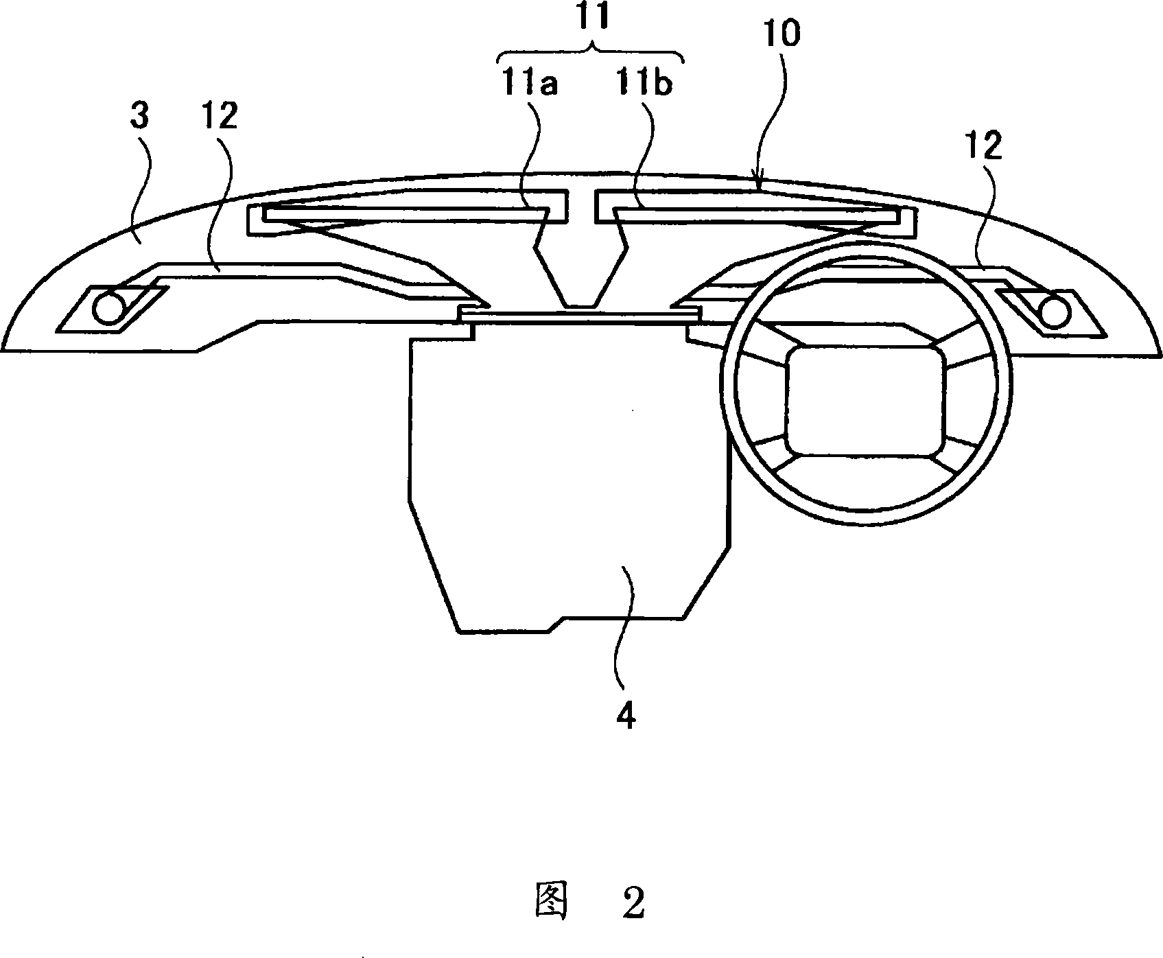
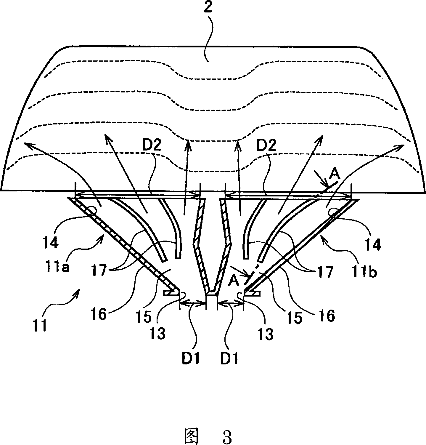
[0028] Next, an embodiment of the present invention will be described with reference to the accompanying drawings. FIGS. 1 to 7 show an embodiment of the present invention. FIG. 1 is a schematic diagram of a vehicle, and FIG. It is the front view of the defroster air supply duct and the front windshield glass, Fig. 4 is the A-A cross-sectional view of Fig. 3, Fig. 5 is the enlarged view of the air direction changing rib, Fig. 6 is the enlarged view of the B part of Fig. 4, and Fig. 7 shows Diagrams of veering flow and cross-rib flow.

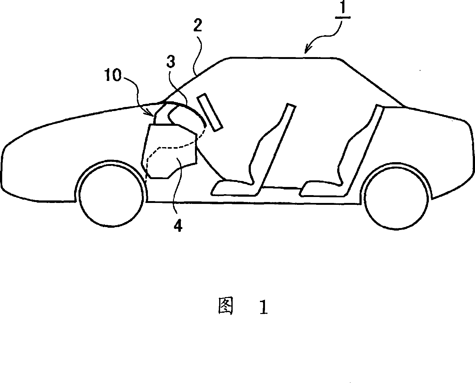
[0029] As shown in FIG. 1 , a vehicle 1 covers the front of its compartment with a windshield glass 2 . An instrument panel 3 is disposed on the vehicle interior side of the lower end of the windshield glass 2 . An air conditioning unit 4 is provided below the instrument panel 3 . The air-conditioning unit 4 generates air-conditioning air at a desired temperature, and the generated air-conditioning air is blown out into the vehicle interior th...


PUM


Abstract

The invention provides an air-blowing duct for a defroster in which a blow-out stream from a blowing port can cover a wide range and a far range and a uniform blow-out distribution is obtained. A duct body 16 in which an air-blowing passage 15 for leading conditioned air introduced from an introduction port 13 to the blowing port 14 is formed inside and the conditioned air is blown out from the blowing port 14 toward a windshield is provided. When an inner surface of the duct body 16 forming the air-blowing passage, i.e., a surface along which a main stream of the conditioned air flows is supposed to be a first surface 16a and the opposed surface is supposed to be a second surface 16b, a wind direction change rib part 17 projected from the first surface 16a toward the second surface 16b and not reaching the second surface 16b is provided.

Description

technical field [0001] The present invention relates to an air supply duct for a defroster for guiding air-conditioning air blown to a front windshield. Background technique [0002] As such a conventional air supply duct for a defroster, there is a duct disclosed in Patent Document 1. As shown in FIG. 9 , this air supply duct 100 for a defroster has a duct main body 101 and a pair of left and right air direction changing ribs 102 and 102 that branch an air supply passage 101 c of the duct main body 101 . The duct main body 101 is formed with an air supply passage 101c whose one end opens as an inlet port 101a and whose other end opens as an air outlet 101b. An air-conditioning unit 103 is connected to the inlet 101a, and the air-conditioning unit 103 introduces air-conditioned air at a desired temperature. The air outlet 101b is opened on the instrument panel (not shown) at the lower end of the windshield (not shown). [0003] The pair of left and right wind direction ch...

Claims


Application Information

Patent Timeline
Patent Type & Authority Applications(China)
IPC IPC(8): B60S1/54
CPCB60H1/3407
Inventor 岛田忠岸宏枥木良一
Owner CALSONIC KANSEI CORP
Why Eureka
Try Eureka