Hand power tool

A hand-held machine tool and motor housing technology, which is applied in the directions of manufacturing tools, striking tools, portable drilling rigs, etc., can solve problems such as vibration failure, and achieve the effects of effective vibration reduction, simple manufacturing and simple structure.

Inactive Publication Date: 2007-12-19
ROBERT BOSCH GMBH
View PDF2 Cites 5 Cited by
  • Summary
  • Abstract
  • Description
  • Claims
  • Application Information

AI Technical Summary

Problems solved by technology

Therefore vibrations cannot or can only be transmitted from the housing part to other parts in a damped manner

Method used


Image

  • Hand power tool
  • Hand power tool

Examples


Embodiment Construction

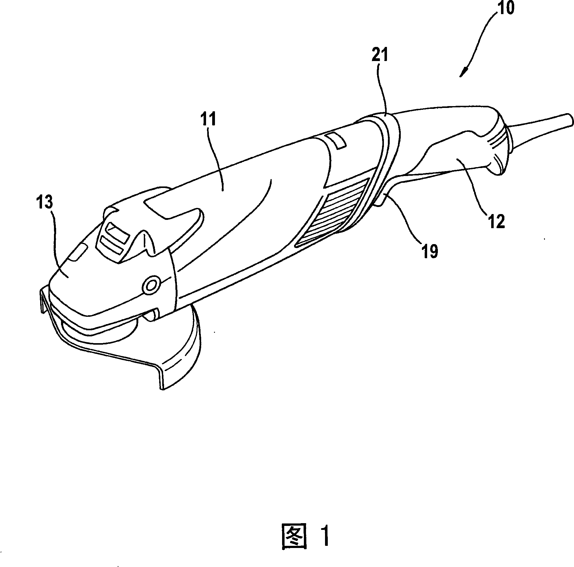
[0023] FIG. 1 shows an angle grinder 10 as an embodiment of the hand power tool according to the invention. In the embodiment shown, the angle grinder 10 comprises three housing parts, a first housing part 11 mainly for accommodating an electric motor (not shown), a second housing designed as a handle 15 Body part 12 and a third housing part 13 mainly for accommodating the transmission (not shown). A drive shaft drivable by the motor 21 is coupled to a driven shaft (not shown) through a transmission consisting of a driving gear and a driven gear. A grinding disc is mounted on the driven shaft (not shown) in a non-rotatable manner. The motor is switched on and off by the user via an on / off switch 19 .

[0024] In the embodiment shown in FIG. 1 , the first housing part 11 and the second housing part 12 are made of plastic, while the third housing part 13 , ie the transmission housing, is made of metal.

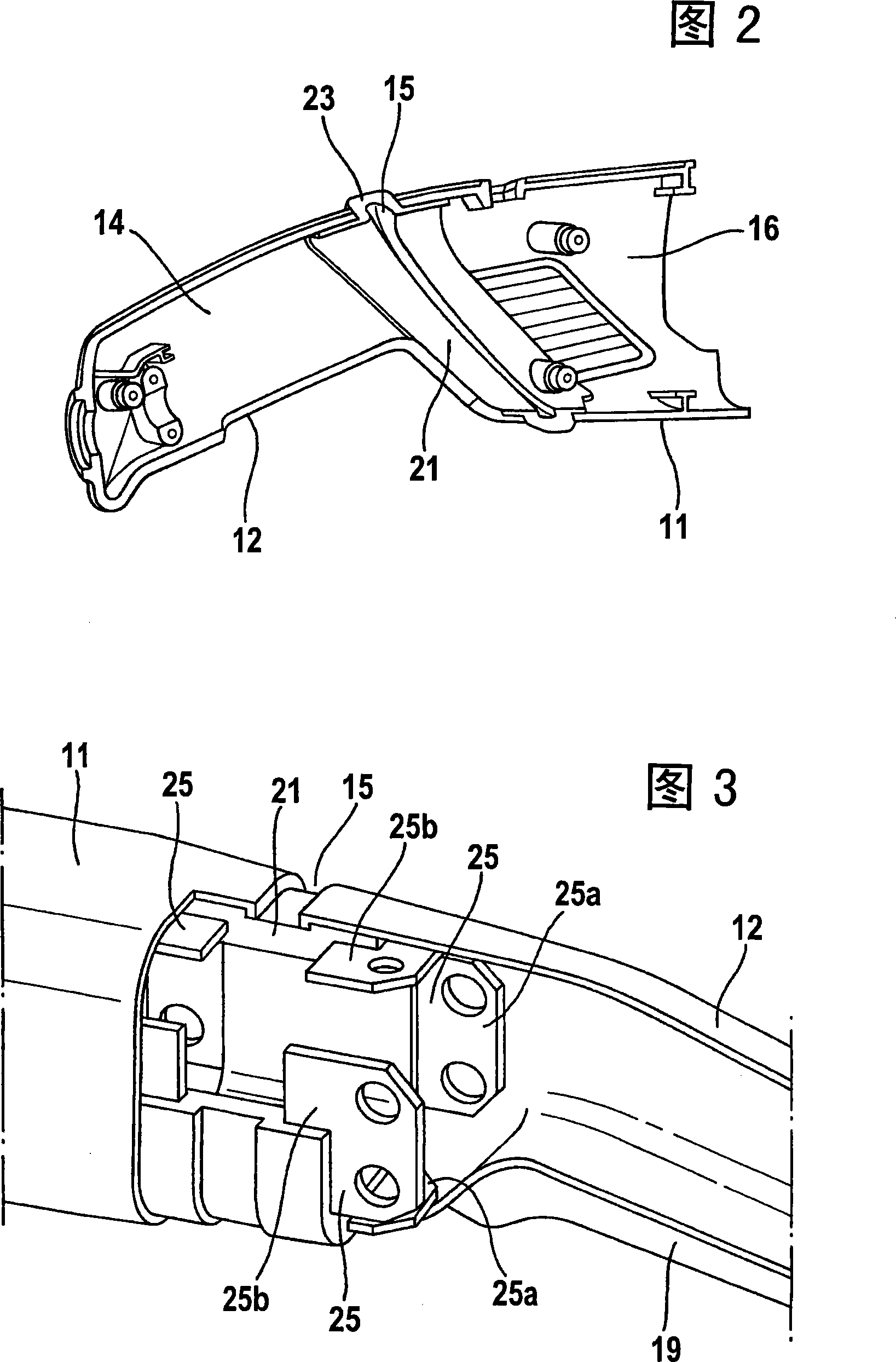
[0025] In the area between the first housing part 11 , the motor housing...


PUM


Abstract

In a hand power tool, including a first housing part and a second housing part as well as a damping element between the first housing part and the second housing part, the damping element is connectable to the first housing part and the second housing part, wherein the first housing part and the second housing part are spaced apart from one another longitudinally of the hand power tool.

Description

technical field [0001] The invention relates to a hand-held power tool comprising a first housing part and a second housing part as well as a damping part between the first housing part and the second housing part, wherein the damping part can be combined with The first housing part and the second housing part are connected. Background technique [0002] When working with electric tools such as angle grinders, drilling machines, hammer drills, strong or not so strong vibrations are mainly caused by the mass rotating at high speed of the motor, transmission, insert tool, etc. Unbalanced and caused by workpiece being machined. The vibration is transmitted through the handle to the operator of the power tool and causes fatigue in the operator's hand. In the case of prolonged work with violently vibrating power tools, there may even be a risk of damage to health. [0003] DE 195 25 251 A describes an oscillating tool with a vibration-insulating ring for isolating the handle f...

Claims


Application Information

Patent Timeline
Patent Type & Authority Applications(China)
IPC IPC(8): B25F5/02B25F5/00B24B23/00B23B45/00B25D16/00B25D17/24
CPCB25F5/006B24B23/00B25F5/02
Inventor J·维克J·沙多J·毛特
Owner ROBERT BOSCH GMBH
Why Eureka
Try Eureka