Emergency release mechanism for automatic transmission

An automatic transmission, emergency unlocking technology, applied in transmission control, components with teeth, belts/chains/gears, etc., can solve the problem that the vehicle cannot be towed away, and achieve simple installation, simple manufacturing, and low cost. the effect of making

Active Publication Date: 2012-11-28
AUDI AG
View PDF6 Cites 4 Cited by
  • Summary
  • Abstract
  • Description
  • Claims
  • Application Information

AI Technical Summary

Problems solved by technology

[0004] In an automatic transmission, when the park lock is engaged, the transmission is locked / jammed, so the vehicle cannot be towed while the shift unit may be malfunctioning

Method used


Image

  • Emergency release mechanism for automatic transmission
  • Emergency release mechanism for automatic transmission
  • Emergency release mechanism for automatic transmission

Examples


Embodiment Construction

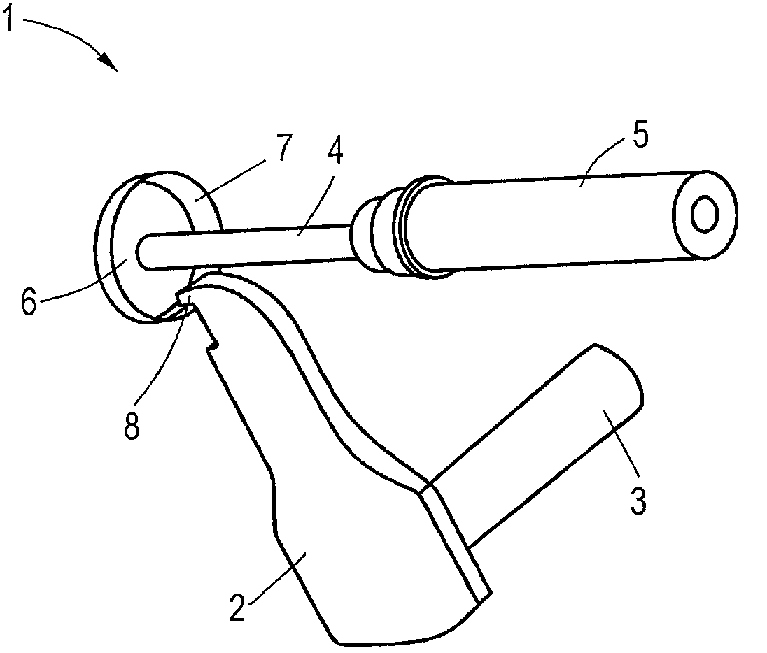
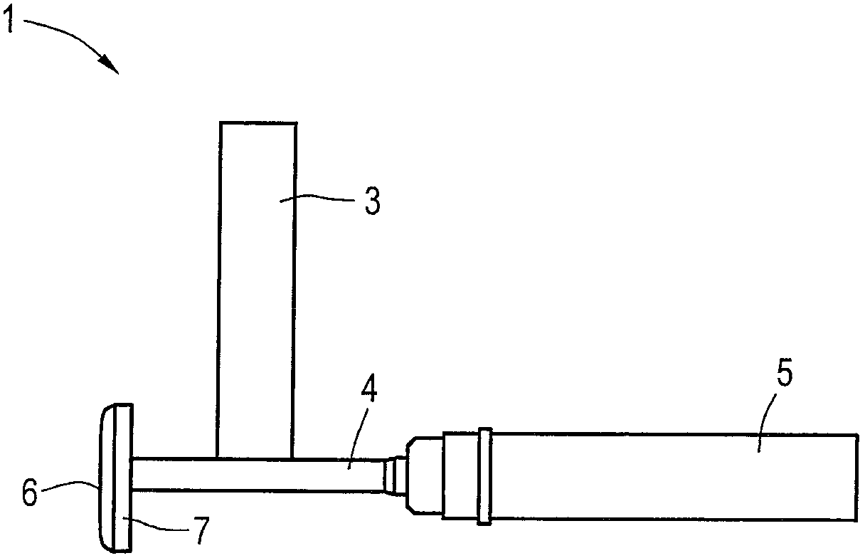
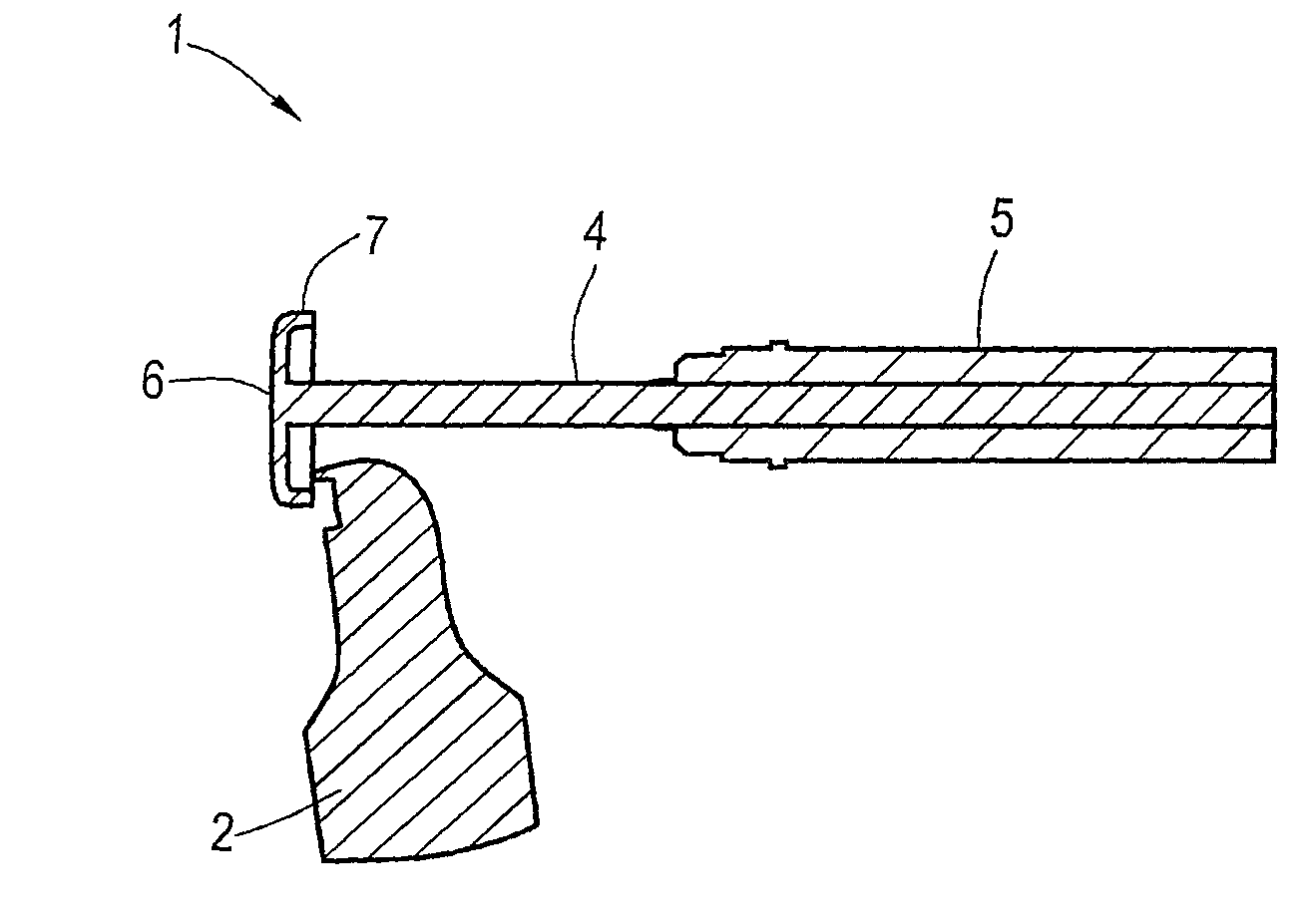
[0025] figure 1 and figure 2 The emergency release device 1 shown is part of a shifting unit of an automatic transmission. The emergency unlocking device 1 comprises a selector lever 2 formed from a flat stamped part. The gear lever 2 has a shaft 3 which forms the axis of rotation of the gear lever 2 . The selector lever 2 is connected via a shaft 3 to an electrohydraulic actuator of the automatic transmission in a known manner. The engaged parking lock is released by turning the selector lever 2 about its axis of rotation. This manual unlocking is only required in the event of a malfunction of the gearshift unit, so that the vehicle can be towed away.

[0026] In addition, the emergency unlocking device 1 comprises a cable 4, figure 1 Only the end section of the cable 4 is shown in . On the opposite end, the user can apply a pulling force to swing the gear lever 2 . Cable 4 is guided in bushing 5 . The enlarged-diameter surface 6 at the end of the cable 4 is designed...


PUM


Abstract

An emergency release mechanism for an automatic transmission has a manually operable cable (4) for moving a control lever (2) for releasing a parking lock inserted in an operating stage. The control lever (2, 12) has a hook- or tooth-shape end section (8, 11) and the cable has a surface (6) at its end with an enlarged diameter, which forms an undercut. The end section of the control lever is engaged in the undercut during the unlocking.

Description

technical field [0001] The invention relates to an emergency unlocking device for an automatic transmission, which has a manually actuatable cable for moving a gear lever and thus releasing a parking lock engaged / engaged in a working stage. Background technique [0002] Automatic transmissions of motor vehicles have shifting units for the selection of various manually preselectable working steps, which are also referred to as driving speed steps / gear steps. The concept of working stages includes all gear stages of the automatic transmission, including the park position and the neutral position. The shifting unit includes a working stage selection element, which is displaceable in a plurality of positions each associated with a working stage. [0003] After the driver has selected a driving speed or working stage, this driving speed or working stage is engaged via electrohydraulic actuators controlled by the transmission controller. [0004] In an automatic transmission, wh...

Claims


Application Information

Patent Timeline
Patent Type & Authority Applications(China)
IPC IPC(8): F16H61/36F16H63/38
CPCF16H61/36F16H63/3491Y10T74/20462
Inventor H·莫克莱恩L·巴鲁斯
Owner AUDI AG
Why Eureka
Try Eureka