Communication system, communication apparatus, and high frequency coupling equipment

A high-frequency coupler and communication system technology, applied in the field of communication systems, can solve the problems of not being suitable for a large amount of data transmission, configuring a large area of ​​coils, and inconvenient use, etc., so as to reduce the risk of cracking information and achieve uniform communication quality Effect

Active Publication Date: 2008-03-19
SONY CORP
View PDF4 Cites 34 Cited by
  • Summary
  • Abstract
  • Description
  • Claims
  • Application Information

AI Technical Summary

Benefits of technology

This patented technology allows two electronic components located far apart without affecting their performance. It uses special techniques called electrical magnetic induction (EMI), which helps transfer wireless signals better through space. Additionally, this technique prevents any unwanted radiation caused by external sources like sunlight while still allowing effective reception of ultraviolet light emissions. Overall, these technical improvements improve the efficiency and reliability of communications within small distances.

Problems solved by technology

This patents discusses various technical features related to electronic communication technologies including near infrared radar technology, ultrasonic sensory communication, etc., particularly in small areas called wearables. These techniques require shorter range connections than traditional wireline networks while maintaining secure communication capabilities. Additionally, they may involve longer ranges beyond 10 mms being passed around during operation. To address these issues, certain embodiments described include short-term communication using an inductive type charging loop technique involving multiple terminals instead of just two connected ones, thereby reducing power consumption and improving performance.

Method used


Image

  • Communication system, communication apparatus, and high frequency coupling equipment
  • Communication system, communication apparatus, and high frequency coupling equipment
  • Communication system, communication apparatus, and high frequency coupling equipment

Examples


Embodiment Construction

[0084] Hereinafter, embodiments of the present invention will be described in detail with reference to the drawings.

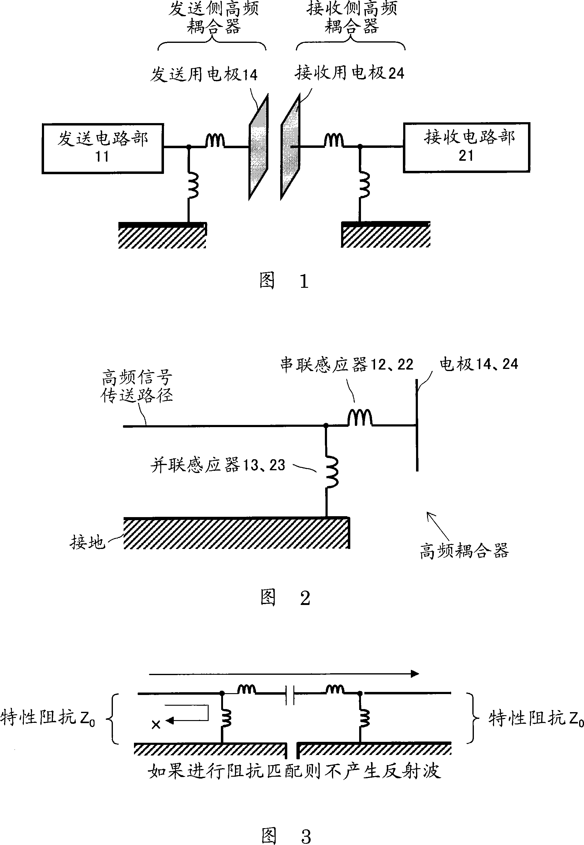
[0085] The invention relates to a communication system for data transmission between information devices by using electrostatic field or induced electric field.

[0086] According to the communication method based on an electrostatic field or an induced electric field, there is no coupling relationship and no radio waves are emitted when there is no communication partner nearby, so it does not interfere with other communication systems. In addition, the coupler does not receive radio waves even if radio waves are transmitted from a distance, so there is no interference from other communication systems.

[0087] In addition, in conventional radio communication using an antenna, the electric field strength of the radiated electric field is inversely proportional to the distance, the electric field strength is attenuated inversely proportional to the square of th...


PUM


Abstract

A communication system includes the following elements: a transmitter including a transmission circuit unit configured to generate an RF signal for transmitting data and an EFC antenna configured to transmit the RF signal as an electrostatic field or an induced electric field; a receiver including an EFC antenna and a reception circuit unit configured to receive and process the RF signal received by the EFC antenna; and an impedance matching unit configured to make an impedance of the EFC antenna of the transmitter equal to an impedance of the EFC antenna of the receiver. The RF signal is transmitted by electric-field coupling between the EFC antennas, facing each other, of the transmitter and the receiver.

Description


Claims


Application Information

Patent Timeline
Owner SONY CORP
Why Eureka
Try Eureka