Knee implant

A technology for implanting prostheses and components, applied in the field of knee joint transplantation, which can solve problems such as expensive, compromising surgical function results, and complexity

Active Publication Date: 2008-04-09
MAKO SURGICAL CORP
View PDF2 Cites 14 Cited by
  • Summary
  • Abstract
  • Description
  • Claims
  • Application Information

AI Technical Summary

Problems solved by technology

Furthermore, larger replacement devices are more complex and / or more expensive than the originally implanted device and / or compromise the functional outcome of the procedure

Method used


Image

  • Knee implant
  • Knee implant
  • Knee implant

Examples


Embodiment Construction

[0049] The preferred embodiments of the present invention are illustrated in the accompanying drawings. The same or similar reference numerals are used throughout the drawings to refer to the same or similar parts.

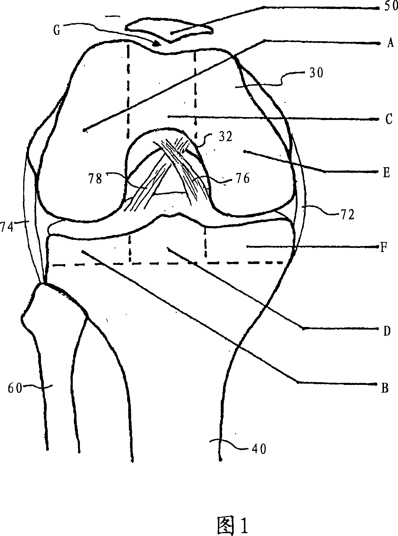
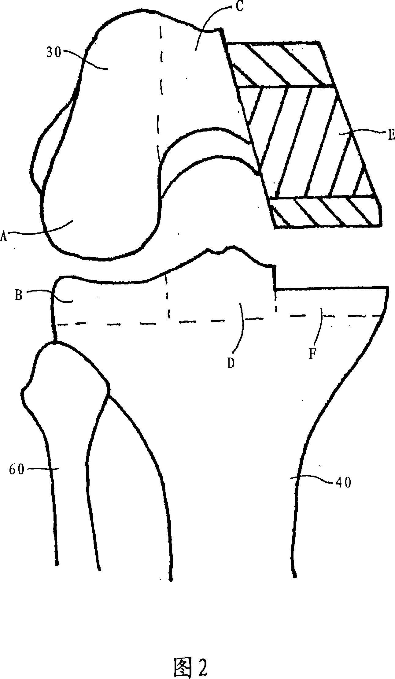
[0050] FIG. 1 is a diagram of a knee joint including the lower end of the femur 30, the upper end of the tibia 40, the fibula 60, and the patella 50. When the knee joint moves, the patella 50 moves relative to the femur 30 and tibia 40. The femur 30 is connected to the tibia 40 by the medial collateral ligament (MCL) 72, the posterior cruciate ligament (PCL) 78, and the anterior cruciate ligament (ACL) 76. The femur 30 is connected to the fibula 60 by the lateral collateral ligament (LCL) 74.

[0051] The lower end of the femur 30 is conceptually divided into a lateral (ie, outer) condyle area A, a middle area C (including the patellar groove 32 having an inverted U shape), and a medial (ie, inner) condyle area E. Similarly, the upper end of the tibia 40 is also conce...


PUM


Abstract

A modular prosthetic device is provided for replacement of the knee. The device is assembled from a plurality of components, each of which can be inserted through a small incision. After inserting the components through the incision, the device can be assembled within the knee cavity. The modularity of the device enables a surgeon to replace only those regions of the knee that are diseased or damaged, thereby avoiding a complete knee replacement. If, at a later time, additional regions of the knee become diseased or damaged, those additional regions of the knee can be replaced by additional device components and those additional components can be connected to the previously implanted components. By replacing only those regions of the knee that are diseased or damaged and by implanting each of the components through the small incision, the surgery is minimally invasive and, therefore, requires reduced time for healing and rehabilitation.

Description

Technical field [0001] The present invention relates to a prosthetic device and related methods for partial or total knee joint replacement. Background technique [0002] It has become a common surgical procedure to partially or completely replace a necrotic and / or damaged knee joint with a suitable prosthesis. It has been found that the result of this surgical operation is advantageous in most cases, and this surgical operation has been regarded as a very advantageous surgical intervention for restoring the function of the knee joint damaged by trauma or degenerative disease. Every year, more than 650,000 patients around the world undergo surgery. Part or all of the knee joints are replaced by implants. These implants are usually able to work normally for 10 years or more. [0003] The traditional implant design includes a tibial component and a femoral component supported on the tibial component. Femoral components are usually made of cobalt-based alloys and are used to replace...

Claims


Application Information

Patent Timeline
Patent Type & Authority Applications(China)
IPC IPC(8): A61F2/38
CPCA61F2002/30604A61F2/38A61F2002/3895
Inventor A·J·T·克莱莫D·C·米尔斯
Owner MAKO SURGICAL CORP
Why Eureka
Try Eureka