Touch sensor track point and methods

一种触摸传感器、指点杆的技术,应用在仪器、计算、电数字数据处理等方向,能够解决指点杆磨损等问题

Inactive Publication Date: 2008-07-09
INT BUSINESS MASCH CORP
View PDF0 Cites 8 Cited by
  • Summary
  • Abstract
  • Description
  • Claims
  • Application Information

AI Technical Summary

Problems solved by technology

[0005] Unfortunately, each of the above pointing sticks requires that the axis of the pointing stick, or the user's finger, move horizontally when pressure is applied to move the computer cursor, which wears out the pointing stick

Method used


Image

  • Touch sensor track point and methods
  • Touch sensor track point and methods
  • Touch sensor track point and methods

Examples


Embodiment Construction

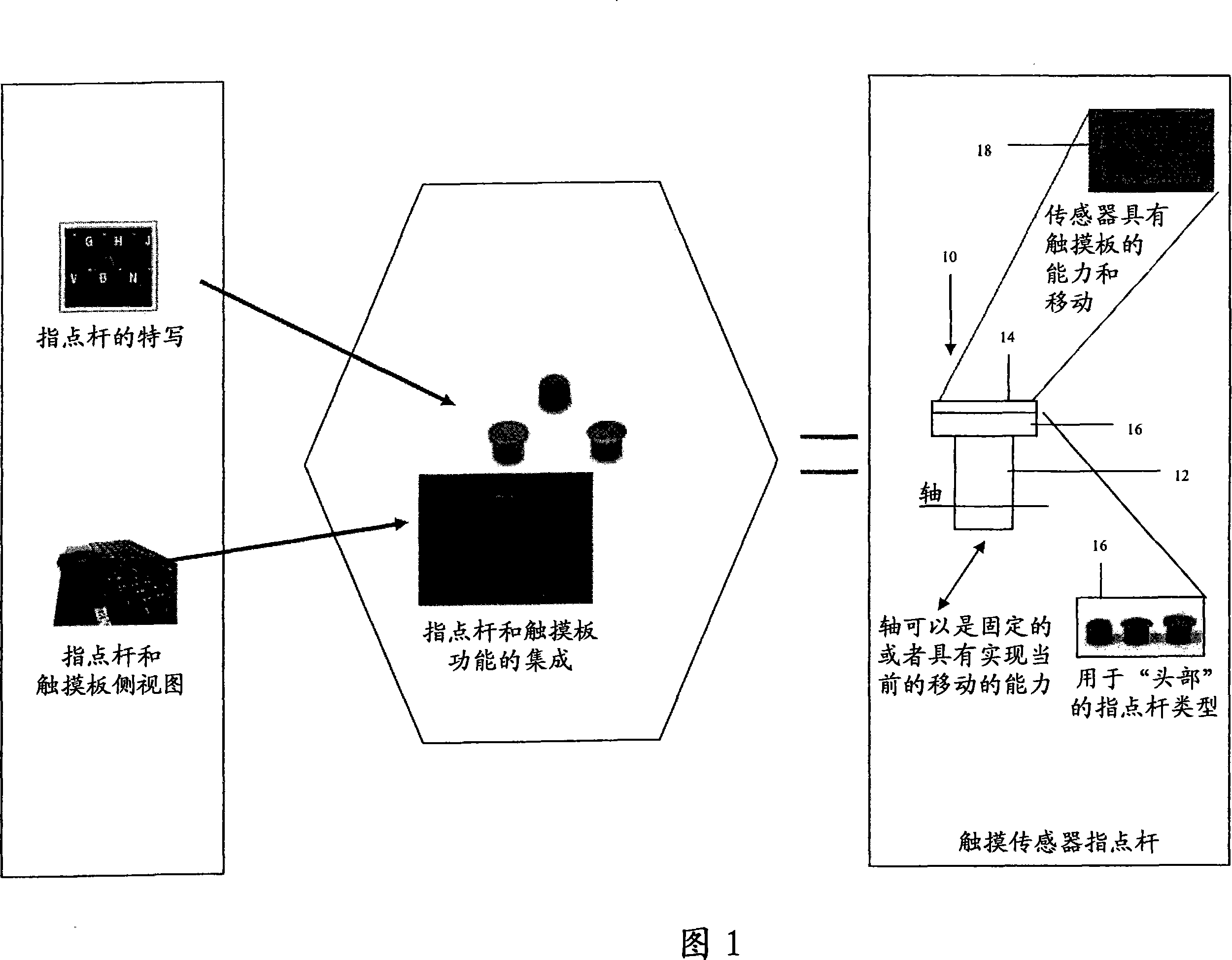
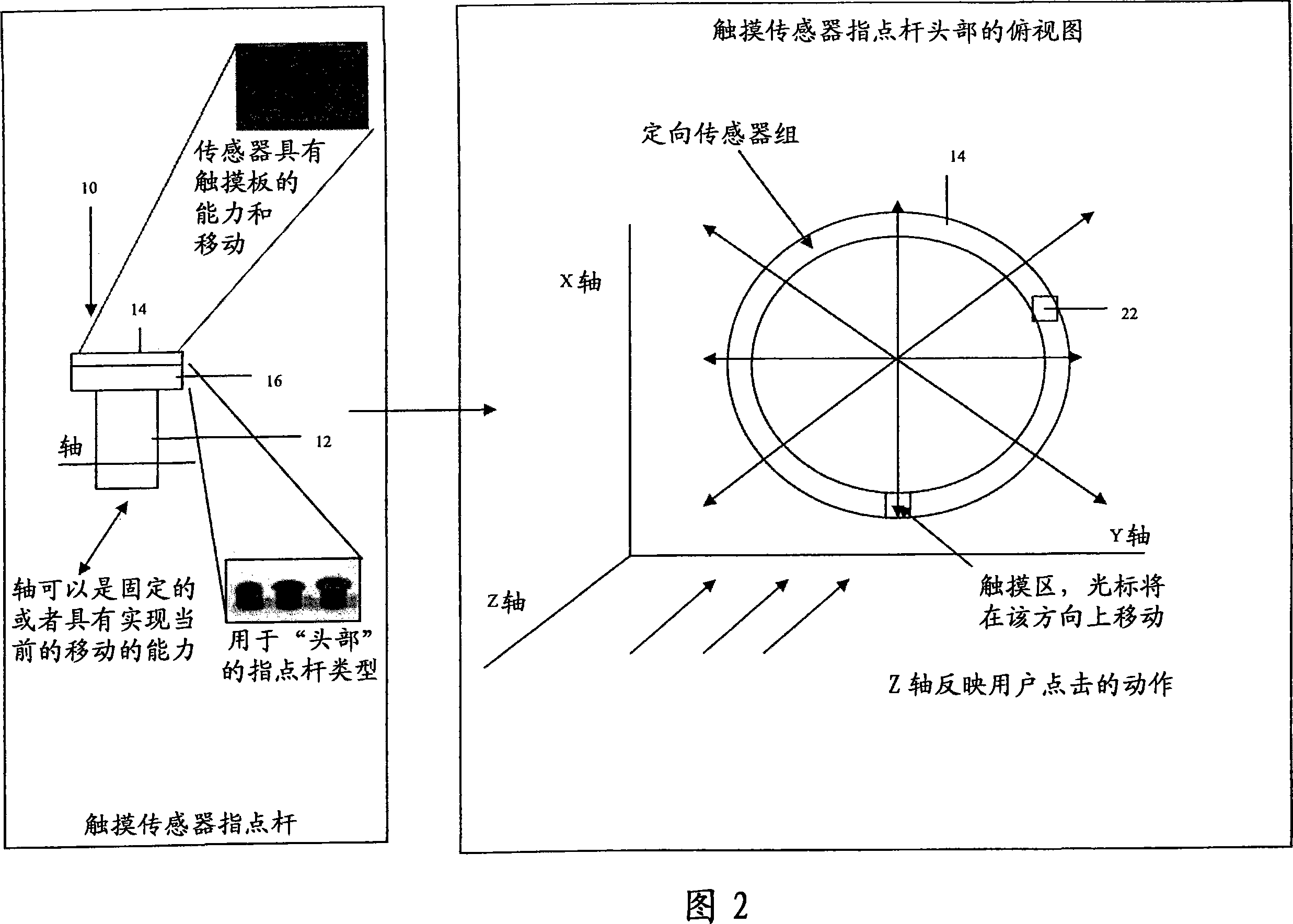
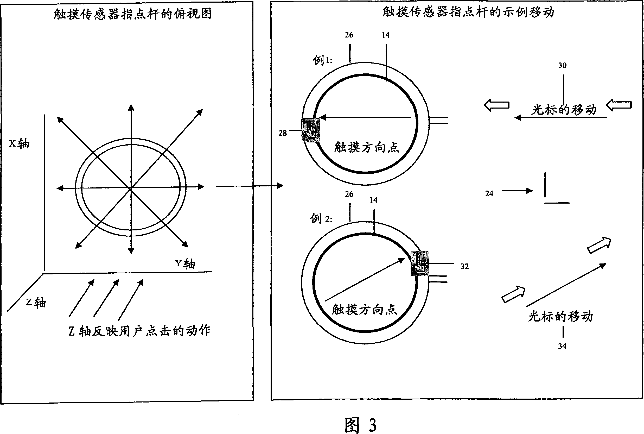
[0016] As indicated above, the present invention provides a touch sensor pointing stick (and method) for a computer such as a laptop computer or portable device (eg, PDA, cell phone, etc.). A touch sensor pointing stick includes a shaft (eg, typically placed on a keyboard) and a set (at least one) of orientation sensors placed on top of the shaft. The set of orientation sensors can detect manipulation in three dimensions (up and down, left and right, and in and out). In a typical embodiment, the touch sensor pointing stick will cause the computer cursor to move in the direction corresponding to the location on the set of orientation sensors where the vertical touch was applied. In such a capability, touches applied to the set of vertical sensors may optionally be substantially horizontally stationary. The set of orientation sensors may also be configured to register / generate a click event in response to a simultaneous vertical press and release of at least one of the set of o...


PUM


Abstract

The present invention provides a touch sensor pointing stick (and method) for a computer such as a laptop computer or portable device (eg, PDA, cell phone, etc.). The touch sensor pointing stick includes a shaft (eg, typically placed on a keyboard) and a set (at least one) of orientation sensors placed on a top surface of the shaft. The set of orientation sensors can detect manipulation in three dimensions (up and down, left and right, and in and out). In typical embodiments, the touch sensor pointing stick will cause the computer cursor to move in a direction corresponding to the location on the set of orientation sensors where a vertical touch is applied. With such capabilities, touches applied to the set of vertical sensors may optionally be substantially horizontally stationary.

Description

technical field [0001] The present invention relates generally to computer cursor manipulation. Specifically, the present invention provides a touch sensor track point and related methods. Background technique [0002] A pointing stick device is located between the G, H and B keys on many laptop / notebook computers. The pointing stick, often referred to as "Little Red Riding Hood," is a key marketing feature of notebooks such as IBM's ThinkPad line of computers (IBM, ThinkPad and related terms are trademarks of IBM Corporation in the United States and / or other countries). Current implementations of the pointing stick make the pointing stick behave like a mouse device in that the computer cursor will move in a direction corresponding to horizontal manipulation of the pointing stick. A pointing stick can be very convenient, yet the size of the pointing stick head is so small that one finger is used to manipulate the pointing stick. To provide additional traction, the head of...

Claims


Application Information

Patent Timeline
Patent Type & Authority Applications(China)
IPC IPC(8): G06F3/033
CPCG06F3/0219G06F3/0338
Inventor 金文柱余德材J·E·小穆尔
Owner INT BUSINESS MASCH CORP
Why Eureka
Try Eureka