
System and apparatus for eyeglass appliance platform

a technology of eyeglass appliance and system, applied in the field of personal multimedia electronic devices, can solve problems such as the disengagement of using these devices

Inactive Publication Date: 2010-05-06
CHAUM DAVID
View PDF14 Cites 709 Cited by
  • Summary
  • Abstract
  • Description
  • Claims
  • Application Information

AI Technical Summary

Benefits of technology

[0141]The eyeglass device of the present invention can be formed as interchangeable components that can be swapped or switched out as desired. For example, in the embodiment of FIGS. 9A-9C, the side arm 914 can be detached from the hinge 929, and a replacement side arm 914′ with one or more different electrical / optical components 930 can be attached. This feature enables the user to switch out side arms to provide different capabilities, as desired. For example, the electrical / optical components 930 on the replacement side arm 914′ can provide capabilities that the user needs only in certain situations, such as a night-vision camera, or a GPS receiver, or other electrical devices with their own unique capabilities. The user can select between a set of various different replacement side arms, depending on which electrical / optical components and capabilities the user needs for a given situation. In one embodiment, a replacement side arm may not have any electrical / optical components, or may have the same functionality as another side arm, but it provides a different style or color or decorative function.

Problems solved by technology

However, the increasing use of these various devices has some disadvantages.
First, many people find that they need to carry multiple different devices with them throughout the day in order to have access to all of the applications that they want to use, such as, for example, a compact digital camera, an MP3 player, a cellular phone, and an automotive GPS unit.
Another disadvantage is the distraction of using these devices while driving, as people may drive recklessly when attempting to locate and use one of these devices.

Method used


Image

  • System and apparatus for eyeglass appliance platform
  • System and apparatus for eyeglass appliance platform
  • System and apparatus for eyeglass appliance platform

Examples


Embodiment Construction

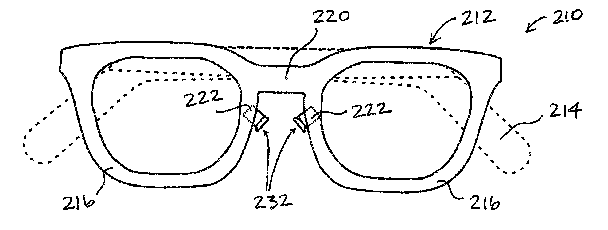
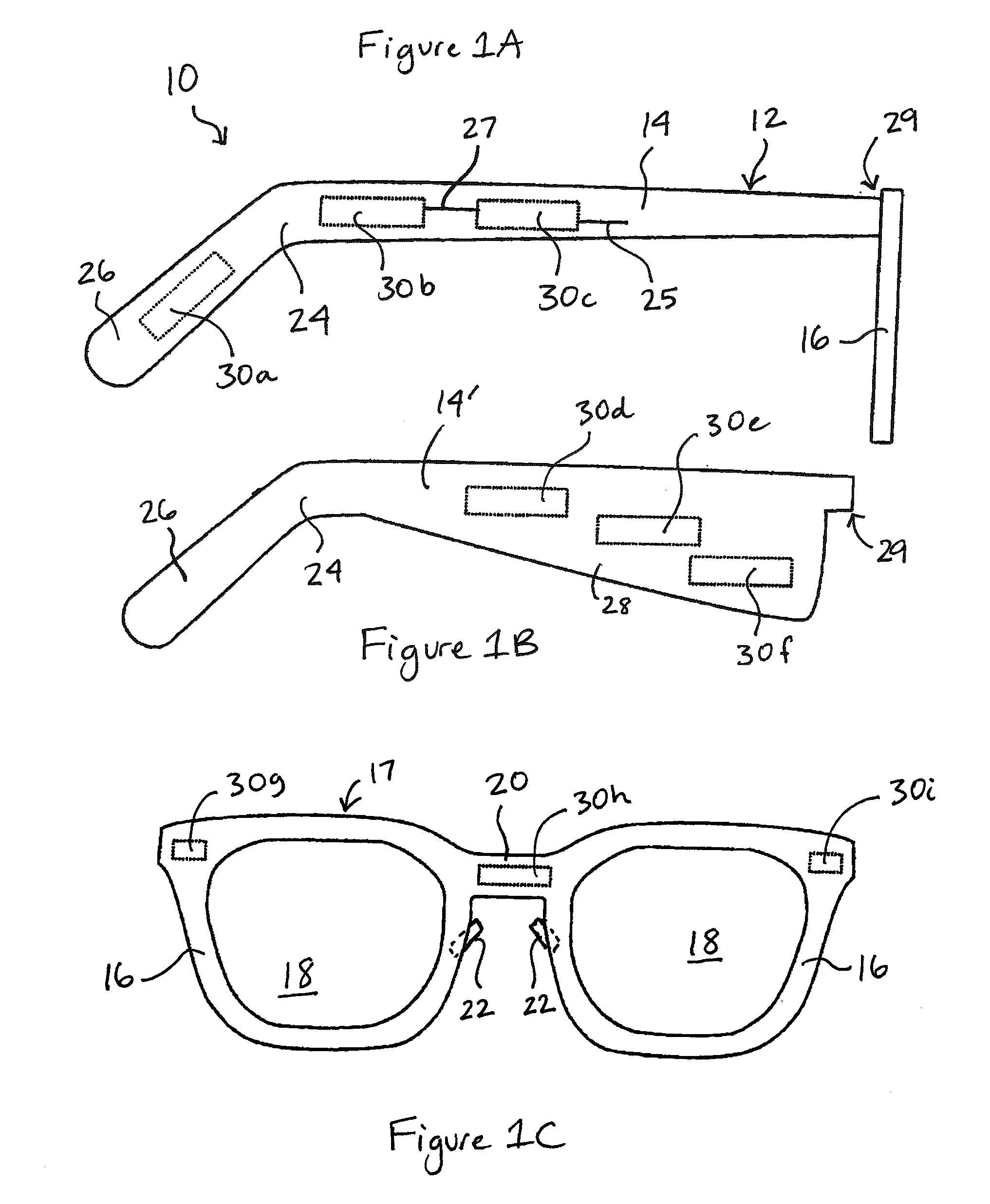
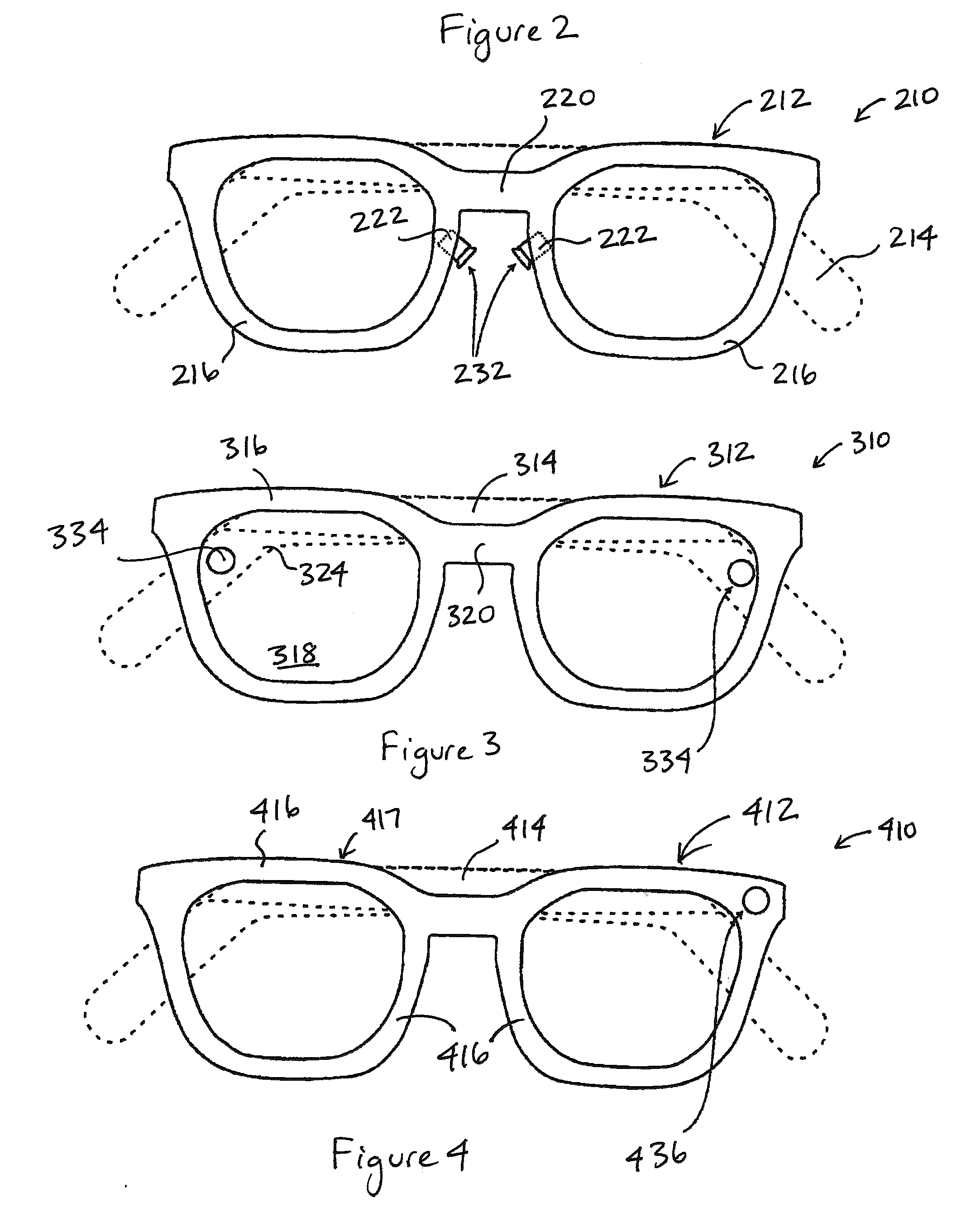
[0065]The present invention relates to a personal multimedia electronic device, and more particularly to a head-worn device such as an eyeglass frame having a plurality of interactive electrical / optical components. In one embodiment, a personal multimedia electronic device includes an eyeglass frame with electrical / optical components mounted in the eyeglass frame. The electrical / optical components mounted in the eyeglass frame can include input devices such as touch sensors and microphones, which enable the user to input instructions or content to the device. The electrical / optical components can also include output devices such as audio speakers and image projectors, which enable the eyeglass device to display content or provide information to the wearer. The electrical / optical components can also include environmental sensors, such as cameras or other monitors or sensors, and communications devices such as a wireless antenna for transmitting or receiving content (e.g., using Bluet...


PUM


Abstract

The present invention relates to a personal multimedia electronic device, and more particularly to a head-worn device such as an eyeglass frame having a plurality of interactive electrical / optical components. In one embodiment, a personal multimedia electronic device includes an eyeglass frame having a side arm and an optic frame; an output device for delivering an output to the wearer; an input device for obtaining an input; and a processor comprising a set of programming instructions for controlling the input device and the output device. The output device is supported by the eyeglass frame and is selected from the group consisting of a speaker, a bone conduction transmitter, an image projector, and a tactile actuator. The input device is supported by the eyeglass frame and is selected from the group consisting of an audio sensor, a tactile sensor, a bone conduction sensor, an image sensor, a body sensor, an environmental sensor, a global positioning system receiver, and an eye tracker. In one embodiment, the processor applies a user interface logic that determines a state of the eyeglass device and determines the output in response to the input and the state.

Description

CROSS-REFERENCE TO RELATED APPLICATION(S)[0001]This application is a continuation-in-part of PCT Application Nos. PCT / US2009 / 002174, entitled “Proximal Image Projection System,” filed Apr. 6, 2009 and PCT / US2009 / 002182, entitled “Proximal Image Projection System,” filed Apr. 6, 2009, the entire contents of which are incorporated by reference herein.[0002]This application claims priority to and the benefit of U.S. Provisional Application Nos. 61 / 042,762, entitled “Proximal-Screen Image Construction,” filed Apr. 6, 2008; 61 / 042,764, entitled “Eyeglasses Enhancements,” filed Apr. 6, 2008; 61 / 042,766, entitled “System for Projecting Images into the Eye,” filed Apr. 6, 2008; 61 / 045,367, entitled “System for Projecting Images into the Eye,” filed Apr. 16, 2008; 61 / 050,189, entitled “Light Sourcing for Image Rendering,” filed May 2, 2008; 61 / 050,602, entitled “Light Sourcing for Image Rendering,” filed May 5, 2008; 61 / 056,056, entitled “Mirror Array Steering and Front-Optic Mirror Arrangem...

Claims


Application Information

Patent Timeline
IPC IPC(8): G02C11/00G06F3/01
CPCG02B27/017G02B2027/0138G02B2027/014G06F3/013G02C11/00G02C11/10G02B2027/0187
Inventor CHAUM, DAVID
Owner CHAUM DAVID
Learn More