
RF home automation system comprising nodes with dual functionality

a home automation and node technology, applied in the direction of electrical programme control, program control, instruments, etc., can solve the problems of low bandwidth, frequency interference, and low data capacity in the amount of data which can be comprised in signals, so as to reduce the cost, improve the quality of the system, and reduce the effect of pri

Inactive Publication Date: 2005-02-15
SILICON LAB INC
View PDF35 Cites 267 Cited by
  • Summary
  • Abstract
  • Description
  • Claims
  • Application Information

AI Technical Summary

Benefits of technology

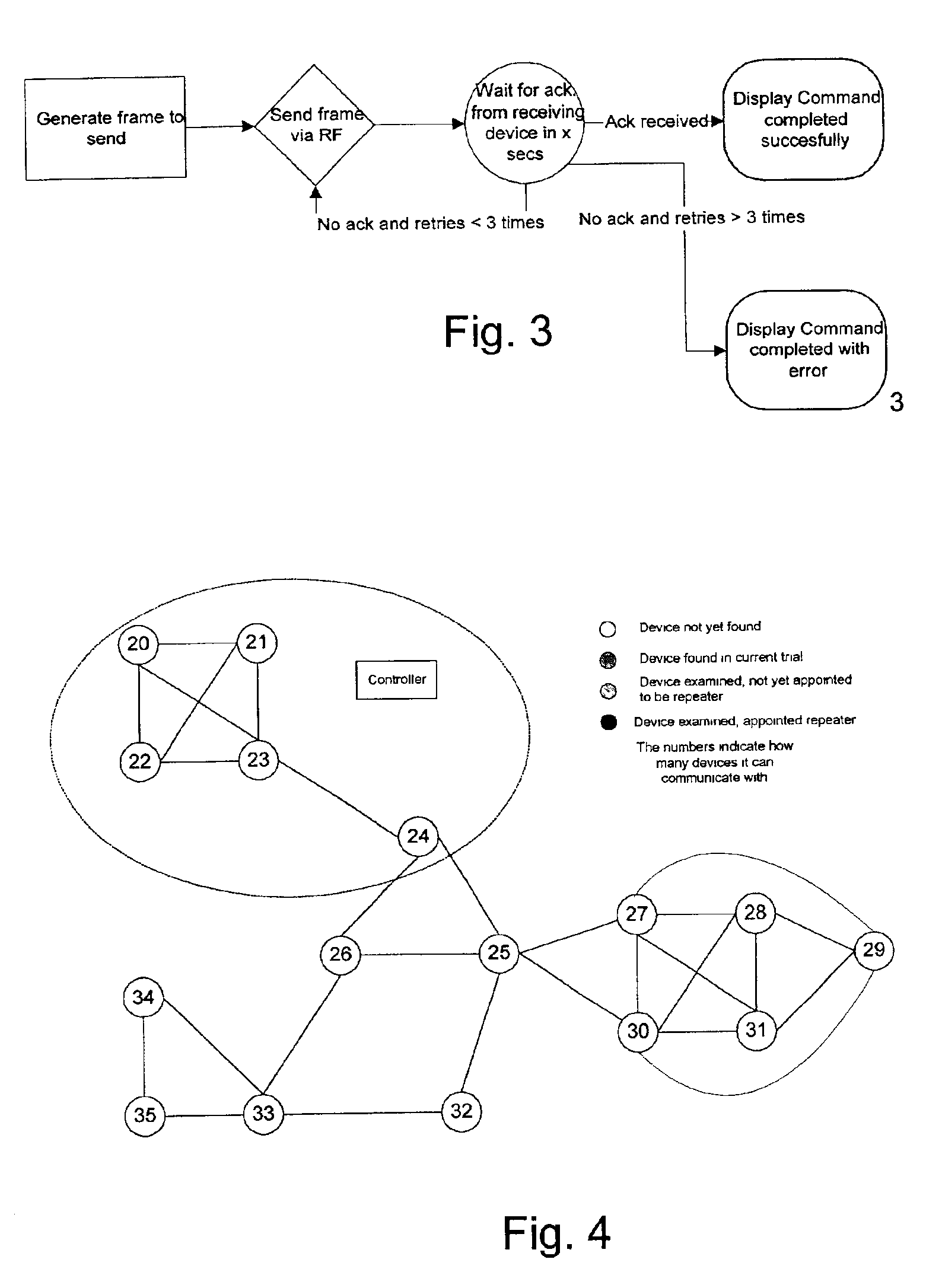
The present invention provides a wireless automation system using radio frequency signals that offers high quality, low cost, and flexibility. The system has a new and inventive routing architecture that allows for more complete and flexible routing schemes. It also uses a low bandwidth for operation, which reduces the price of chips and allows for more devices in the network. The system is optimized to ensure reliability, range, versatility, and flexibility. It is flexible to a dynamically changing topology and can act as a repeater device for other devices. The system also provides a large and dynamic range of coverage without the need for dedicated repeater stations. Overall, the system provides a high-quality, low-cost, and flexible wireless automation solution.

Problems solved by technology

However, choosing low bandwidth operation in a public frequency range introduces a number of problems which may reduce the quality of the system:A low bandwidth gives a low capacity in the amount of data which can be comprised in signals.A large number of apparatuses operate in public frequency ranges resulting in a large amount of radio frequency interference.The allowed transmission power of RF transmitters is restricted which results in a limited signal range.

Method used


Image

  • RF home automation system comprising nodes with dual functionality
  • RF home automation system comprising nodes with dual functionality
  • RF home automation system comprising nodes with dual functionality

Examples


first embodiment

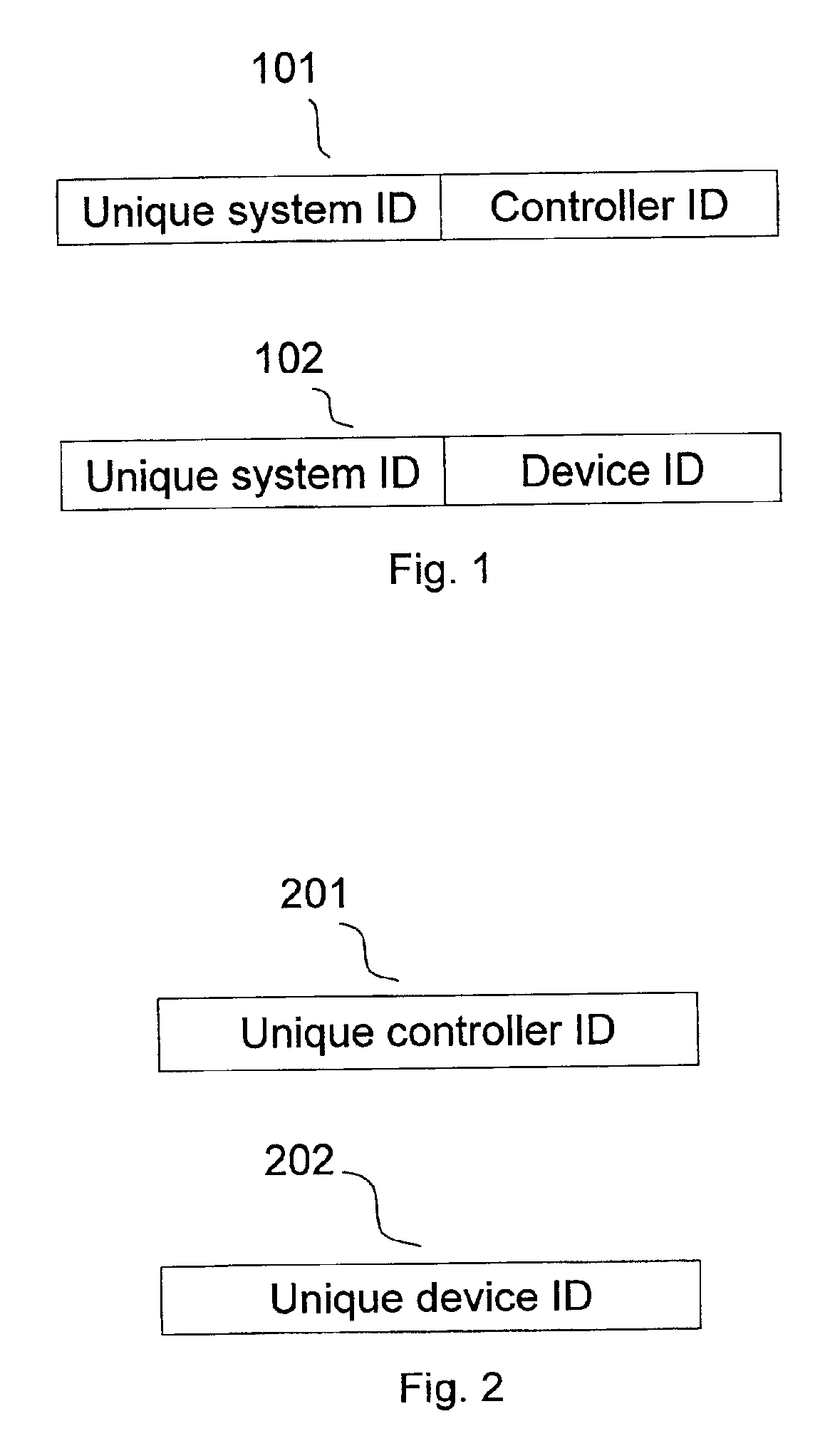
The communication protocol of the first embodiment has a general format for the frames carrying the instructions and information between the devices of the system.

The frame format according to the first embodiment can be described as:

TABLE 1

Wherein:The numbers 0 through 15 represent a bit-scale giving the order and sizes of each part of the frame. The order in which the parts appear are not restrictive and different orders can be used.Home ID (32 bit): The Home ID of the system in which this frame should be executed / received.Source ID (8-bit): The identifier (second part of the two-part identifier) of the transmitting controller or device.Version (3 bit): Protocol / frame format version. This gives the freedom to change the frame format according to an update of the software protocol or other infrastructure enhancements.Dir. (1 bit): Direction of command; 0 when a command is issued, 1 when a command is acknowledged.Type (4 bit): The type of frame decides the contents of the rest of th...

second embodiment

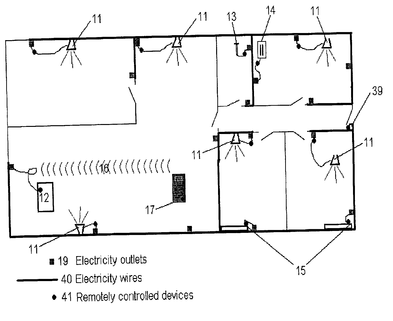
The following description of the Power & Lighting control system mainly deals with those aspects not comprised in the high-level description of general parts of the conceptual, scaleable system given in the description of the first preferred embodiment of the automation system. However, details and features described only in relation to the second embodiment are also valid with respect to the first preferred embodiment.

The Power & Lighting control system consists of the following elements.

Controllers

In the Power & Lighting embodiment, the controller is a mobile control panel such as a remote control, so that the use or programming of the system is not restricted to certain locations. Controllers have a display such as an LCD (Liquid Crystal Display) display. The controllers can optionally interface with a computer; moreover, a computer may also act as a controller in the system. The initial implementation and often also later setting of a device is carried out in the vicinity of the...


PUM


Abstract

The present invention relates to a wireless home automation system having a controller for controlling a broad variety of functions via two ways communication with a plurality of devices. The controllers and devices of the system comprises means for generating a signal comprising a destination identifier, instructions related to the input / output of the destination or source device, and a repeater identifier. The devices according to the invention are adapted to act as input / output devices and signal repeating devices. The processors of each device comprises means for, upon reception of a signal, processing said information if the destination identifier corresponds to the device identifier of the device, and means for, upon reception of a signal, transmitting a second signal holding at least said destination identifier and said instruction if the repeater identifier corresponds to the device identifier of the device.

Description

FIELD OF THE INVENTIONThe present invention relates to a wireless home automation system having a controller for controlling a broad variety of functions via two ways communication with a plurality of devices. More specifically, the invention relates to a new and flexible way of establishing a wireless network by using devices which functions as both input / output devices and repeaters. By establishing an even distribution of these dual-functionality devices, the user can reach any device without use of dedicated repeater stations.BACKGROUND OF THE INVENTIONHome automation systems for controlling devices with various functions such as lighting and audio equipment within a building has evolved towards a “smart-home” concept, where different input / output (I / O) devices with a wide range of functions are remotely controlled by a central controller. Such systems are constructed as networks with a plurality of nodes which can be controllers, I / O devices, or dedicated signal repeaters or am...

Claims


Application Information

Patent Timeline
Patent Type & Authority Patents(United States)
IPC IPC(8): G05B19/04G05B19/042G05B15/02H04Q9/00G05B9/03
CPCG05B15/02G05B19/0426G05B2219/21042G05B2219/21073G05B2219/25081G05B2219/37252G05B2219/25196G05B2219/25208G05B2219/25211G05B2219/2642G05B2219/32234G05B2219/25181H04B7/15507
Inventor CHRISTENSEN, CARLOS MELIAKNUDSEN, JESPER
Owner SILICON LAB INC
Learn More