Portable telephone in a security network

a security network and portable technology, applied in data switching networks, testing/monitoring control systems, instruments, etc., can solve the problems of inconvenient installation of security systems, inability to drill holes for hardwiring, and inability to maintain inventive systems permanently, etc., and achieve high reliability.

Inactive Publication Date: 2009-03-31
ADT US HLDG INC
View PDF173 Cites 183 Cited by
  • Summary
  • Abstract
  • Description
  • Claims
  • Application Information

AI Technical Summary

Benefits of technology

[0016]To achieve these and other objects, and in view of its purposes, the present invention provides a highly reliable system and method for constructing a security network, or security system, for a building comprising a network of devices and using a novel approach to designing base units and transponders to provide the radio link between each of a number of openings and a controller function capable of causing an alert in the event of an intrusion. Some forms of the present invention may also provide cordless telephone functionality and may further be packaged in an embodiment familiar to many end users as a cordless telephone system.
[0017]The present invention improves upon the traditional system model and paradigm by providing a security network with reliability exceeding that of existing wireless security systems, at lower cost than either professionally installed hardwired systems or wireless security systems. The present invention also allows self-installation, including incremental expansion, by typical homeowners targeted by the major home improvement and electronics retail chains.
[0018]Several new marketing opportunities are created for a security network that are otherwise unavailable in the market today. First, for professional systems sold by major alarm companies, a single customer service representative may sell the network to a homeowner and then install the network in a single visit to the customer's home. This is in contrast to the present model where a salesperson sells the system and then an installer must return at a later date to drill holes, pull wires, and otherwise install the system. Second, there is a product upgrade available for existing systems whereby the scope of security coverage can be increased by adding base units and transponders to an existing control panel. Third, homeowners may purchase the inventive system at a home improvement chain, self-install the system, and contract for alarm monitoring from an alarm services company. The overall system cost is lower, and the alarm services company is not required to underwrite initial installation costs, as is presently done today. Therefore, the alarm services company can offer monitoring services at substantially lower prices. Fourth, a new market for apartment dwellers opens up. Presently, very few security systems are installed in apartments because building owners are unwilling to permit the drilling of holes and installation of permanent systems. Apartment dwellers are also more transient than homeowners and therefore most apartment dwellers and alarm service companies are unwilling to underwrite the cost of these systems anyway. The inventive system is not permanent, nor is drilling holes for hardwiring required. Therefore, an apartment dweller can purchase the inventive security network, use it in one apartment, and then unplug and move the network to another apartment later.
[0019]The improvements provided by the present invention are accomplished through the following innovations. The first innovation is the design of a low cost base unit that can cover an area of a house. Rather than rely on the single centrally located transceiver approach of existing unreliable wireless security systems, the present invention allows the placement of multiple base units into multiple rooms and areas for which coverage is desired. The presence of multiple base units within a building provides spatial receiver diversity.
[0022]The fourth innovation is the optional inclusion of a glass breakage or motion sensor into the base unit. In many applications, a base unit will likely be installed into multiple rooms of a house. Rather than require a separate glass breakage or motion sensor as in prior art security systems, a form of the base unit includes a glass breakage or motion sensor within the same integrated package, providing a further reduction in overall system cost when compared to prior art systems.
[0023]The fifth innovation is the permitted optional use of the traditional public switched telephone network (i.e., PSTN—the standard home phone line), the integrated use of a commercial mobile radio service (CMRS) such as a TDMA, GSM, or CDMA wireless network, or the use of a broadband internet network via Ethernet or WiFi connection for causing an alert at an emergency response agency such as an alarm service company. In particular, the use of a CMRS network provides a higher level of security, and a further ease of installation. The higher level of security results from (i) reduced susceptibility of the security system to cuts in the wires of a PSTN connection, and (ii) optional use of messaging between the security system and an emergency response agency such that any break in the messaging will in itself cause an alert.

Problems solved by technology

Third, homeowners may purchase the inventive system at a home improvement chain, self-install the system, and contract for alarm monitoring from an alarm services company.
Presently, very few security systems are installed in apartments because building owners are unwilling to permit the drilling of holes and installation of permanent systems.
The inventive system is not permanent, nor is drilling holes for hardwiring required.

Method used


Image

  • Portable telephone in a security network
  • Portable telephone in a security network
  • Portable telephone in a security network

Examples


Embodiment Construction

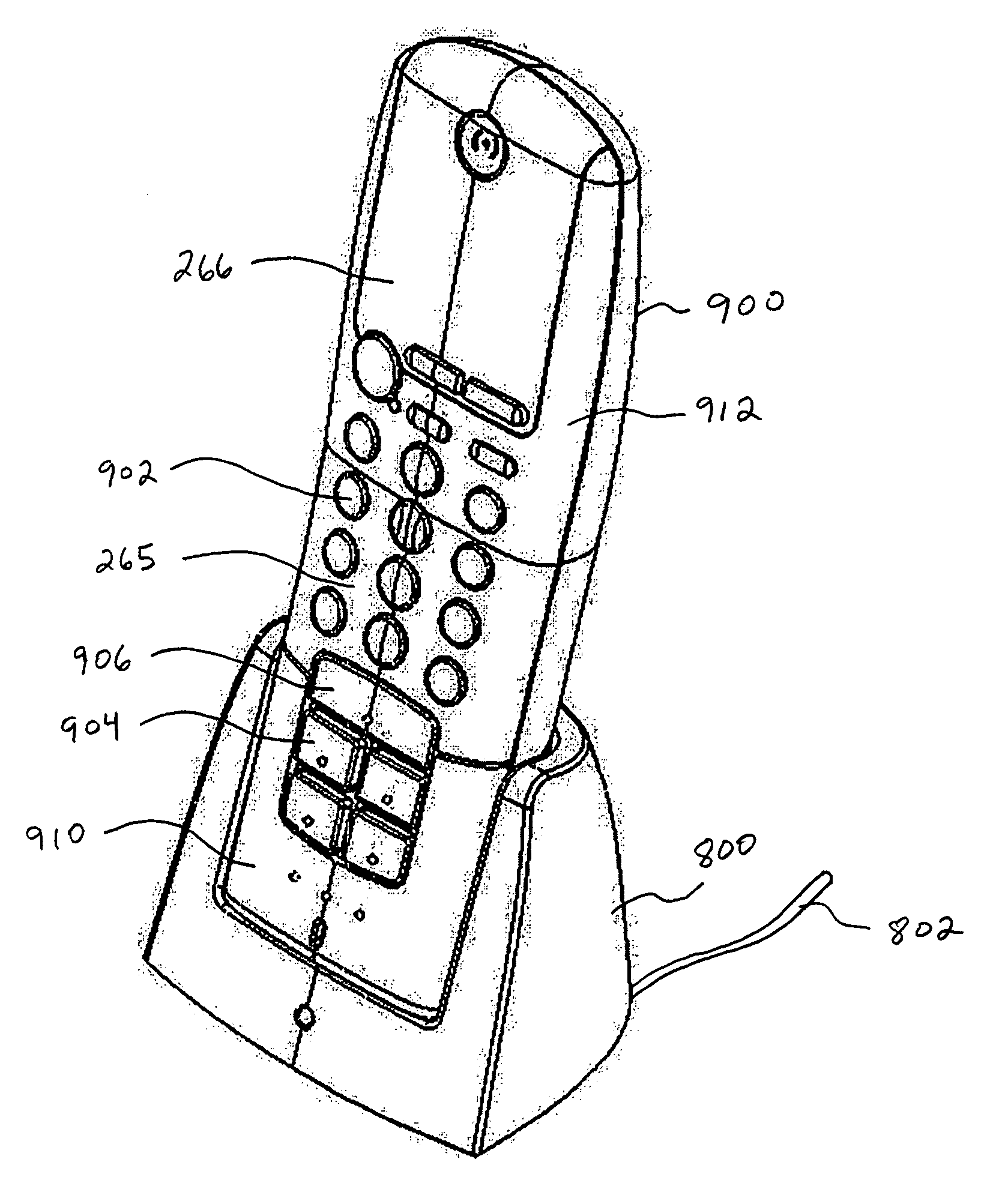
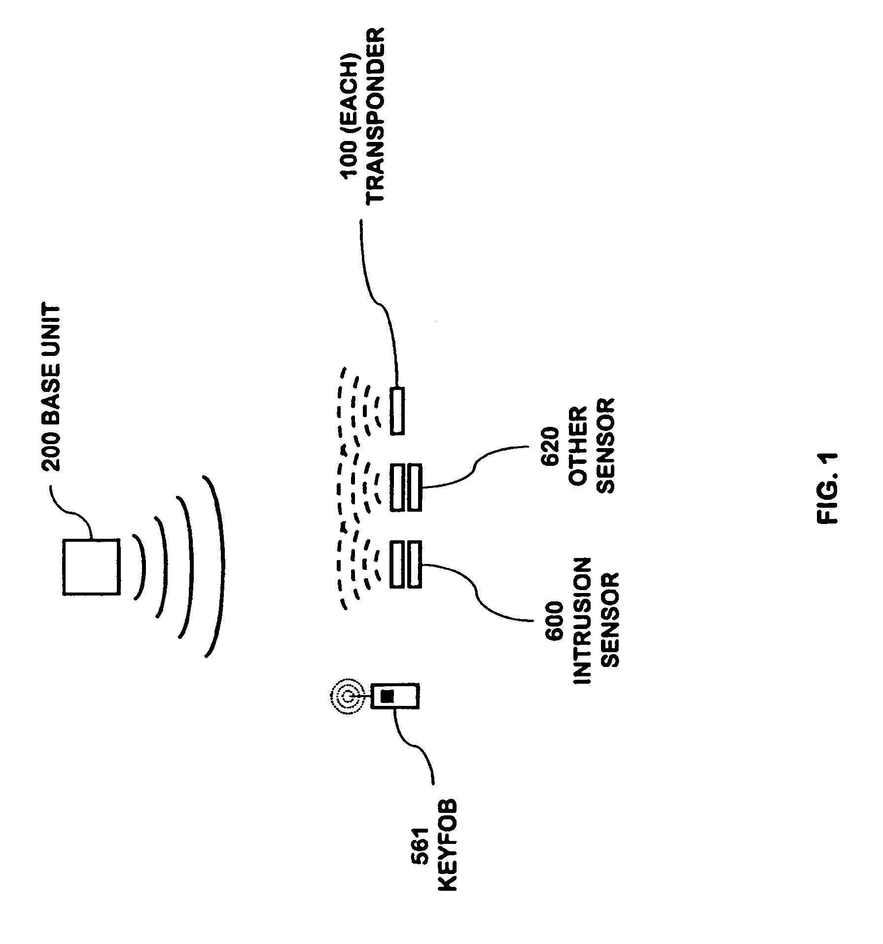
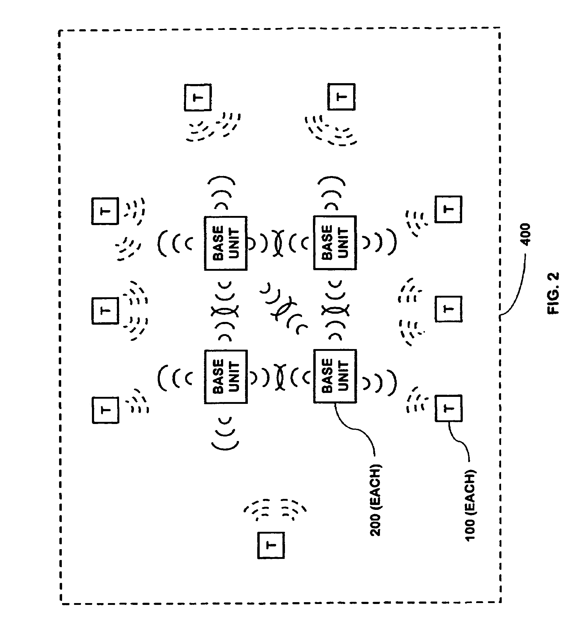
[0060]The present invention is a highly reliable system and method for constructing a security network 400, or security system, for use in a building, such as a commercial building, single or multifamily residence, or apartment. For consistency with the cross referenced applications, the term security system may be used sometimes, though in the context of this present application, the terms security system and security network 400 shall be considered interchangeable as they apply to the present invention. The security network 400 may also be used for buildings that are smaller structures such as sheds, boathouses, other storage facilities, and the like. Throughout this specification, a residential house will be used as an example when describing aspects of the present invention. However, the present invention is equally applicable to other types of buildings. Some forms of the present invention may also provide cordless telephone functionality and may further be packaged in an embod...


PUM


Abstract

A security network for use in a building with an opening to be monitored for possible intrusion. The network includes an intrusion sensor monitoring the opening; an RFID transponder associated with the sensor; an RFID reader in wireless communication with the transponder; and a portable telephone handset having first keys activating conventional telephone capability and second keys activating interaction with the other security network components. The handset wirelessly communicates with the reader. The reader may take the form of a security cradle for the handset. Alternatively, the reader may take the form of a telephone console. The console has keys enabling a user to dial remote telephone numbers; circuitry adapted to receive wireless communications from the transponder; circuitry in wireless communication with the handset; circuitry in communication with an external network; and a processor executing program code enabling the handset to communicate with the external network via the telephone console.

Description

[0001]This patent application is a continuation-in-part of U.S. application Ser. No. 10 / 821,938, Cordless Telephone System, filed Apr. 12, 2004 by the inventor of the present application and now issued as U.S. Pat. No. 7,042,353, which is itself a continuation-in-part of U.S. application Ser. No. 10 / 795,368, Multi-Controller Security Network, filed Mar. 9, 2004 and now issued as U.S. Pat. No. 7,079,020, which is itself a continuation-in-part of U.S. application Ser. No. 10 / 602,854, RFIID Reader for a Security Network, filed Jun. 25, 2003 and now issued as U.S. Pat. No. 7,023,341, which is itself a continuation-in-part of U.S. application Ser. No. 10 / 423,887, RFID Based Security Network, filed Apr. 28, 2003 and now issued as U.S. Pat. No. 7,019,639, which is itself a continuation-in-part of U.S. application Ser. No. 10 / 366,316, RFID Reader for a Security System, filed Feb. 14, 2003 and now issued as U.S. Pat. No. 7,057,512, which is itself a continuation-in-part of U.S. application S...

Claims


Application Information

Patent Timeline
Patent Type & Authority Patents(United States)
IPC IPC(8): G08B13/00G06K7/00G08B1/00G08B19/00G08B25/00G08B25/10G08B29/14
CPCG05B9/03H04W12/12G06K7/0008G08B13/248G08B19/005G08B25/009G08B25/08G08B25/10G08B29/06G08B29/14H04L12/2803H04L12/2825H04M3/12G08B25/008G05B15/02H04M2242/04H04W24/02H04W88/08H04L63/1408G08B25/002H04W12/122H04W12/126
Inventor STILP, LOUIS A.DODDS, LARRY V.
Owner ADT US HLDG INC
Why Eureka
Try Eureka