
Electronic device having display and surrounding touch sensitive bezel for user interface and control

a touch sensitive bezel and display technology, applied in the field of electronic devices having a display and a surrounding touch sensitive bezel for user interface and control, can solve the problems of affecting the numerous possible functions, the way inputs are made into the device, and the separation of hand-held electronic devices in limited ways

Active Publication Date: 2010-02-02
APPLE INC
View PDF255 Cites 726 Cited by
  • Summary
  • Abstract
  • Description
  • Claims
  • Application Information

AI Technical Summary

Benefits of technology

This solution enables a more streamlined user interface with reduced physical buttons, allowing for a larger display and improved one-handed operation by utilizing touch-sensitive technology and orientation sensing to dynamically adjust control layouts.

Problems solved by technology

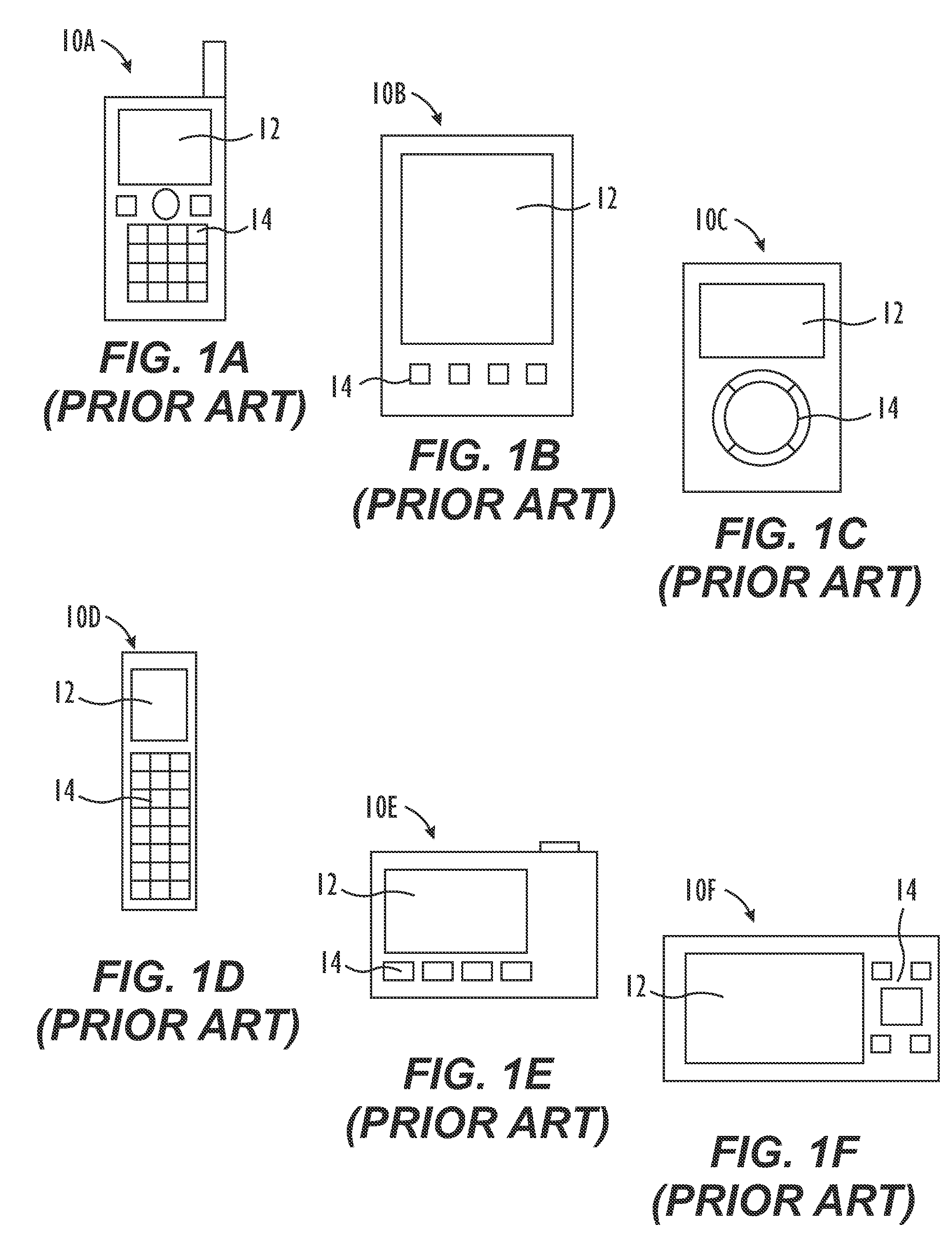
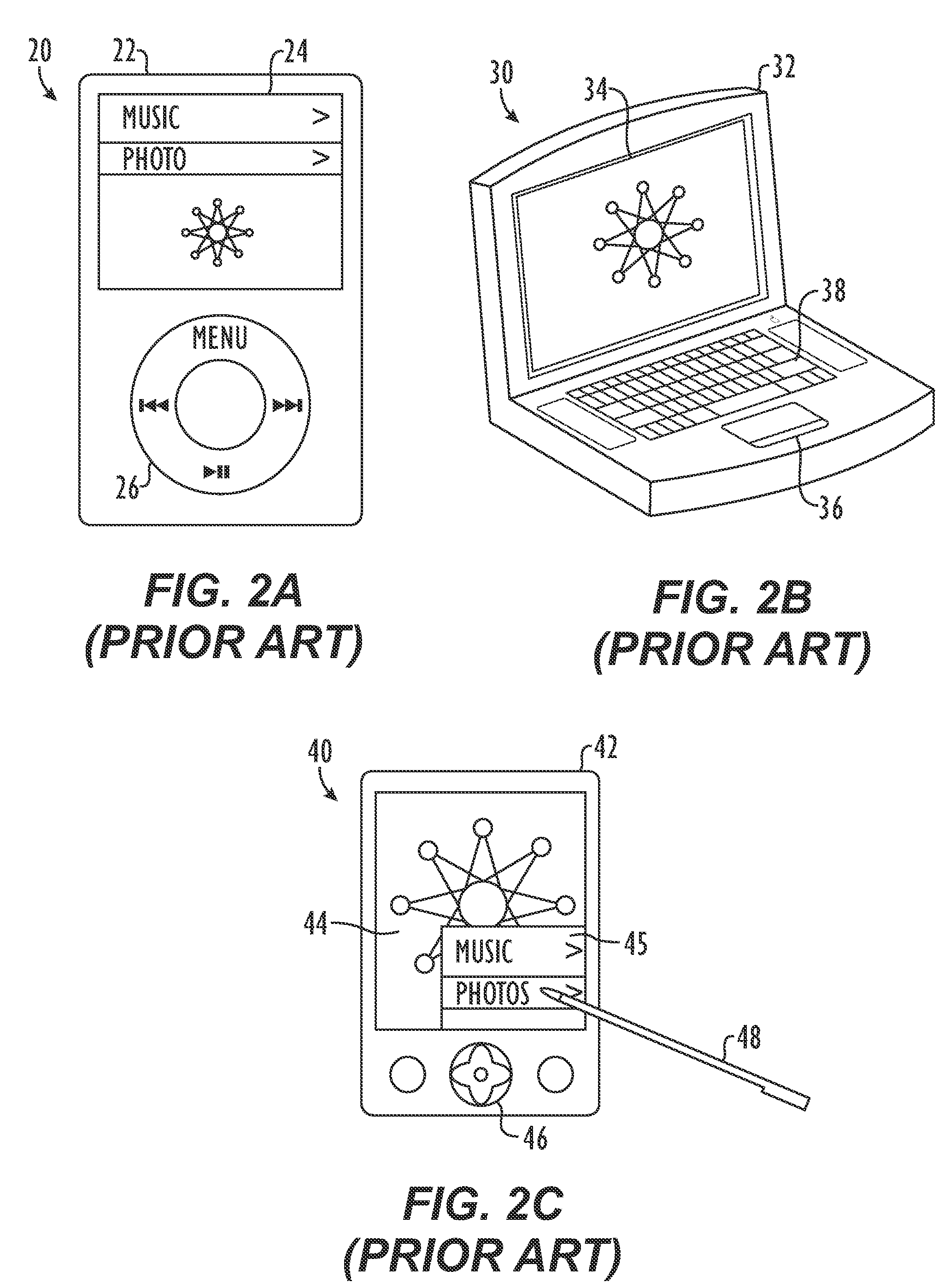
Recently, traditionally separate hand-held electronic devices have begun to be combined in limited ways.
One problem that has been encountered is in the way inputs are made into the device.
Thus, it is a challenge to design a device with limited input mechanisms without adversely affecting the numerous possible functions that the device can perform.
At some point, there is not enough space on the device to house all the necessary buttons and switches, etc.
This is especially true when considering that all these devices need a display that typically takes up a large amount of space on its own.
However, this will often leave a negative impression on the user because the user typically desires the largest display possible.
This, too, will often leave a negative impression on a user because it would make one-handed operations difficult, and at some point, the size of the device becomes so large that it is no longer considered a hand-held device.

Method used


Image

  • Electronic device having display and surrounding touch sensitive bezel for user interface and control
  • Electronic device having display and surrounding touch sensitive bezel for user interface and control
  • Electronic device having display and surrounding touch sensitive bezel for user interface and control

Examples


Embodiment Construction

[0039]Co-pending U.S. patent application Ser. No. 11 / 367,749, which has been incorporated herein by reference in its entirety, discloses electronic devices capable of configuring user inputs based on how the devices are to be used. The electronic devices may be multi-functional hand-held devices. The electronic devices have a user interface that requires no (or at most only a few) physical buttons, keys, or switches so that the display size of the electronic devices can be substantially increased. Preferably, the electronic devices eliminate such physical buttons, keys, or switches from a front surface of the electronic device so that additional surface area becomes available for a larger display on the electronic device. Ultimately, this strategy allows the electronic device to house a substantially full screen display. As used herein, a full screen display is a display that consumes, or at least dominates, a surface (e.g., a front surface) of the electronic device.

[0040]FIG. 3A is...


PUM


Abstract

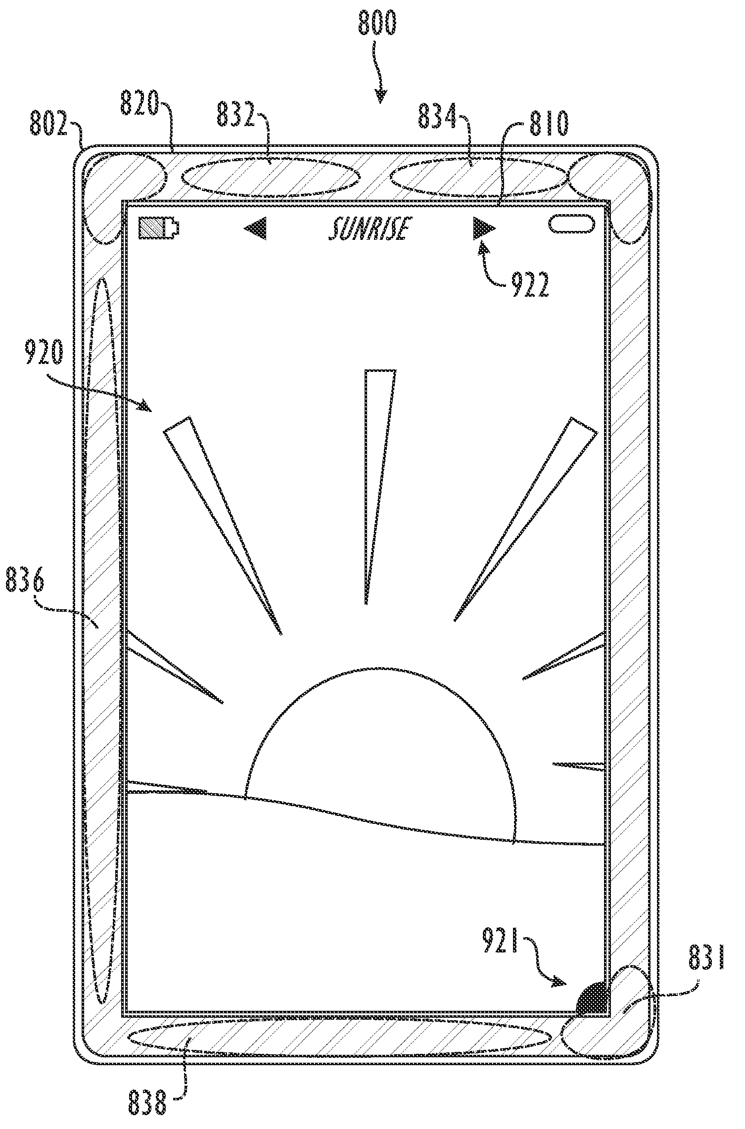
An electronic device has a display and has a touch sensitive bezel surrounding the display. Areas on the bezel are designated for controls used to operate the electronic device. Visual guides corresponding to the controls are displayed on the display adjacent the areas of the bezel designated for the controls. Touch data is generated by the bezel when a user touches an area of the bezel. The device determines which of the controls has been selected based on which designated area is associated with the touch data from the bezel. The device then initiates the determined control. The device can have a sensor for determining the orientation of the device. Based on the orientation, the device can alter the areas designated on the bezel for the controls and can alter the location of the visual guides for the display so that they match the altered areas on the bezel.

Description

CROSS-REFERENCE TO RELATED APPLICATIONS[0001]This is a continuation-in-part of U.S. patent application Ser. No. 11 / 367,749, filed Mar. 3, 2006 and entitled “Multi-Functional Hand-Held Device,” which is incorporated herein by reference in its entirety, to which priority is claimed, and which claims priority to: (1) U.S. Provisional Patent Application No. 60 / 658,777, entitled “Multi-Functional Hand-Held Device,” filed Mar. 4, 2005 and (2) U.S. Provisional Patent Application No. 60 / 663,345, entitle titled “Multi-Functional Hand-Held Device,” filed Mar. 16, 2005, each of which is hereby incorporated by reference.[0002]This application is also related to the following applications, which are all herein incorporated by reference: (1) U.S. patent application Ser. No. 10 / 188,182, entitled “Touch Pad for Handheld Device,” filed on Jul. 1, 2002; (2) U.S. patent application Ser. No. 10 / 722,948, entitled “Touch Pad for Handheld Device,” filed on Nov. 25, 2003; (3) U.S. patent application Ser. N...

Claims


Application Information

Patent Timeline
Patent Type & Authority Patents(United States)
IPC IPC(8): G06F3/041A61M37/00G09G5/00H04B1/40G06F3/045G06F3/02
CPCG06F1/1626G06F1/1637G06F1/169G06F3/04883G06F3/04886G06F3/044G06F2203/04808G06F3/04847G06F2203/0339G06F3/0446G06F3/0445G06F2203/04105G06F1/1643G06F3/03547G06F3/0412G06F2200/1612G06F2203/04101
Inventor KING, NICKKERR, DUNCANHERBST, PAULHOTELLING, STEVEN P
Owner APPLE INC
Learn More