
238 U fission ionization chamber for measuring 20MeV energy zone neutron fluence rate
A technology of neutron fluence rate and ionization chamber, which is applied in the field of ionization chamber devices, can solve the problems of high cost and achieve the effect of reducing costs
- Summary
- Abstract
- Description
- Claims
- Application Information
AI Technical Summary
Problems solved by technology
Method used
Image

Examples
Embodiment Construction
[0010] Below in conjunction with accompanying drawing and specific embodiment the present invention is described in further detail:
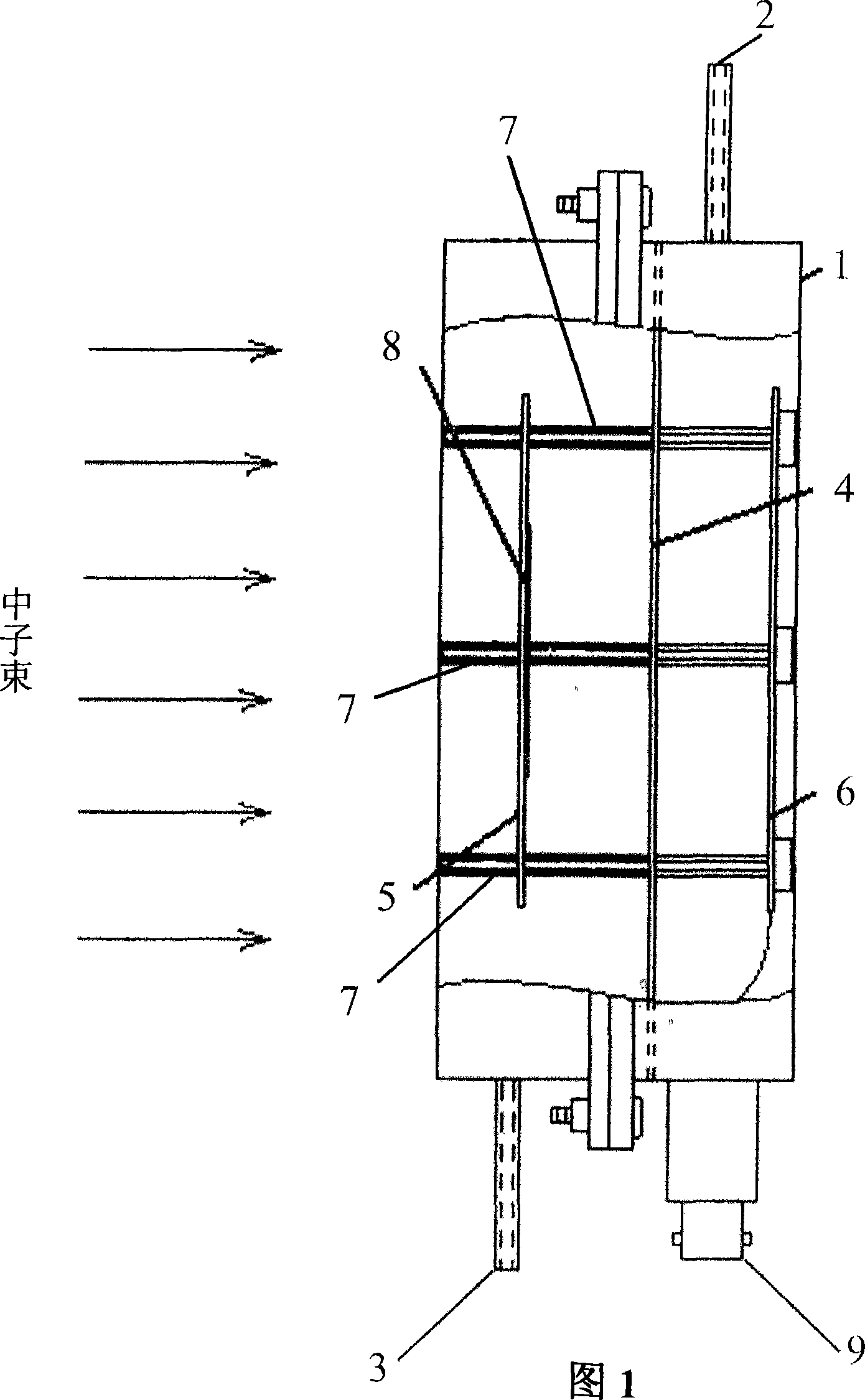
[0011] The device has a columnar structure, including a shell 1 with an inner diameter of 170mm and a front and rear wall thickness of 1.1mm. The shell 1 is welded with an air inlet 2 and an air outlet 3, and a stainless steel substrate 5 with a diameter of 150mm and a thickness of 0.4mm. And the collector 6 with a diameter of 150 mm and a thickness of 0.3 mm is fixed inside the shell 1 through a stainless steel fixing ring 4 and a pillar 7 composed of a polytetrafluoroethylene rod and a sleeve, and the stainless steel bottom lining 5 and the shell 1 are connected through a brass sleeve The tube is connected as the cathode, and the collector 6 is insulated from the shell 1 through the polytetrafluoroethylene sleeve and used as the anode. 238 The U sample 8 is electroplated on the substrate 5 , and the signal collected by the collector 6 is trans...
PUM
 Abstract
Description
Claims
Application Information