Device for improving pipe and gas-solid circumfluence bed coupling reaction

The technology of a reaction device and a riser is applied in the directions of fluidized bed combustion equipment, lighting and heating equipment, combustion methods, etc., and can solve the problems that the riser is difficult to meet the reaction requirements, the storage capacity of the riser is difficult, and the particle residence time is short, etc. Achieve the effect of reducing resistance, improving stability, and uniform gas-solid contact

Active Publication Date: 2008-09-10
CHINA UNIV OF PETROLEUM (BEIJING)
View PDF0 Cites 19 Cited by
  • Summary
  • Abstract
  • Description
  • Claims
  • Application Information

AI Technical Summary

Problems solved by technology

But at the same time, there are some unfavorable factors such as small particle concentration in the bed, less back-mixing, short particle residence time, low calorific value per unit mass of particles, low feeding rate, and difficult to maintain stable storage capacity in the riser. Disadvantages of combustion of petroleum coke or gasification waste coke
[0005] The above two types of reactions, one is for gas-phase processing, the other is for solid-phase processing, both require a long reaction time, and at the same time must ensure the system pressure balance or cycle rate requirements, a single boost Tube or fluidized bed reactor are difficult to meet the reaction requirements, riser and conventional fluidized bed coupling reactor also has some shortcomings

Method used


Image

  • Device for improving pipe and gas-solid circumfluence bed coupling reaction
  • Device for improving pipe and gas-solid circumfluence bed coupling reaction
  • Device for improving pipe and gas-solid circumfluence bed coupling reaction

Examples


Embodiment 1

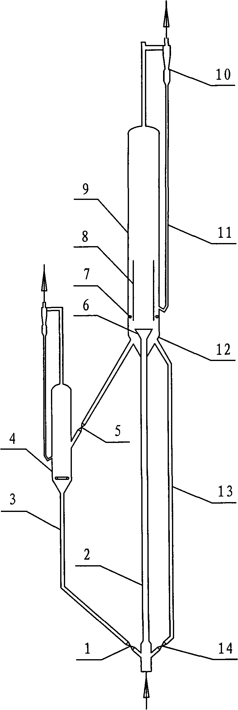
[0027] See attached figure 1 , The riser and gas-solid annular fluidized bed coupling reaction device of this embodiment includes: riser 2, external circulation pipe 3, external circulation fluidized bed 4, showerhead distributor 6, annulus gas distribution ring 7, and guide tube 8. Outer cylinder 9, gas-solid separator 10, material leg 11, inverted cone 12, internal circulation pipe 13, and control valves 1, 5 and 14. The outlet end of the riser 2 extends into the inverted cone 12 at the lower part of the outer cylinder 9 of the circulation bed, and the outlet end is connected with the shower head distributor 6 which is placed in the lower part of the outer cylinder 9 of the circulation bed or the inverted cone 12 in. The guide tube 8 adopts a single-stage form and is arranged above the shower head distributor 6, in order to ensure that the annulus particles flow smoothly into the guide tube 8, and at the same time to make the annulus flow into the projection area below the guid...

Embodiment 2

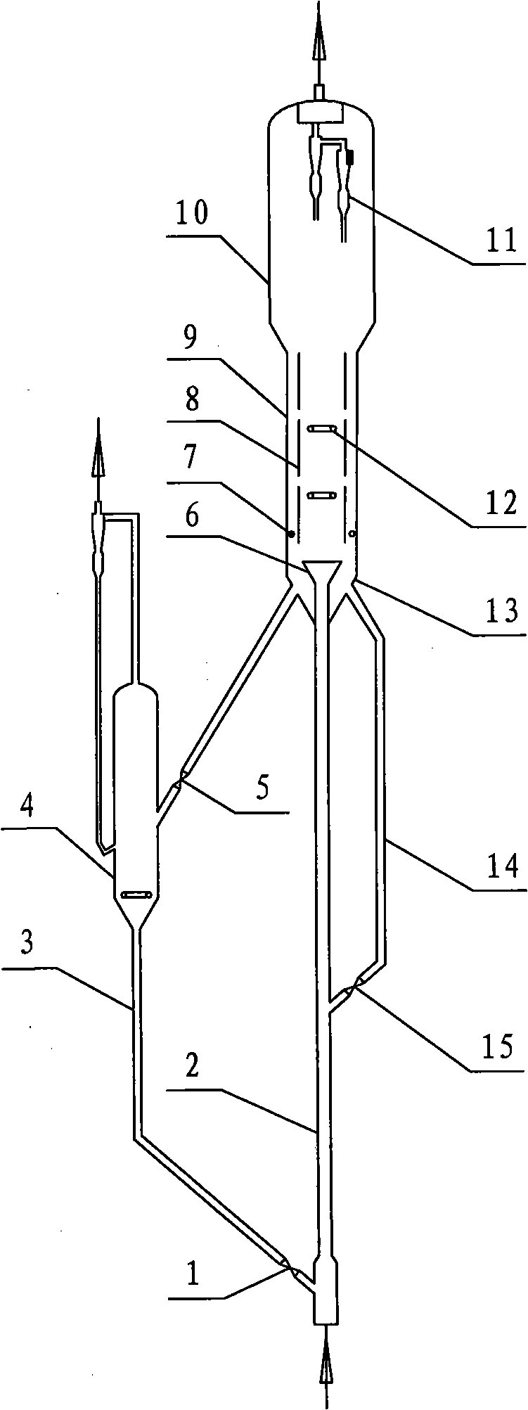
[0032] See attached figure 2 , The riser and gas-solid annular fluidized bed coupling reaction device of this embodiment includes: riser 2, external circulation pipe 3, external circulation fluidized bed 4, showerhead distributor 6, annulus gas distribution ring 7, and guide tube 8. Circulating bed outer cylinder 9, settlement space outer cylinder 10, gas-solid separator 11, auxiliary gas distribution ring 12, inverted cone 13, internal circulation pipe 14 and control valves 1, 5 and 15. The outlet end of the riser 2 extends into the inverted cone 13 at the lower part of the outer cylinder 9 of the circulation bed, and the outlet end is connected with the shower head distributor 6 which is placed in the lower part of the outer cylinder 9 of the circulation bed or the inverted cone 13 in. The guide tube 8 adopts an equal-diameter straight cylindrical multi-section guide tube, which is arranged above the shower head distributor 6 to ensure that the annulus particles flow smoothly i...

Embodiment 3

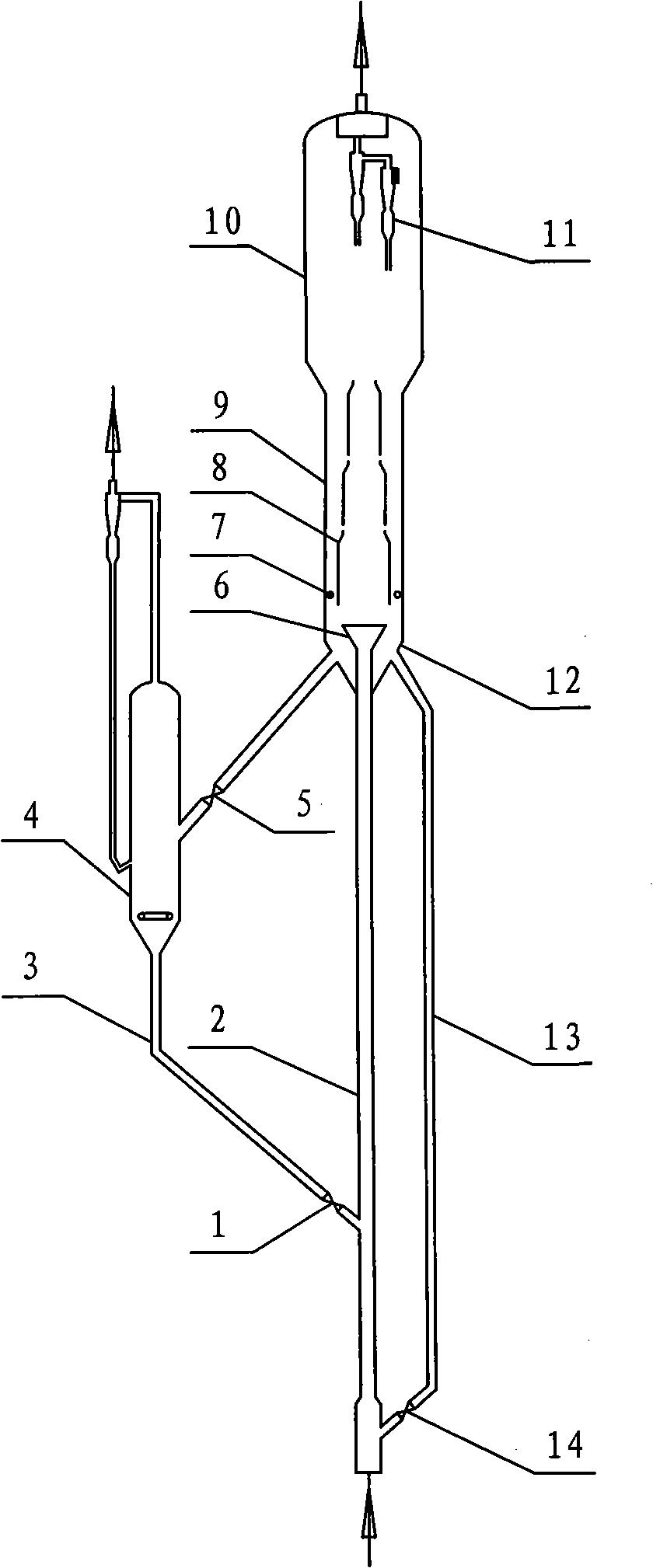
[0037] See attached image 3 , The riser and gas-solid annular fluidized bed coupling reaction device of this embodiment includes: riser 2, external circulation pipe 3, external circulation fluidized bed 4, showerhead distributor 6, annulus gas distribution ring 7, and guide tube 8. Circulating bed outer cylinder 9, settlement space outer cylinder 10, gas-solid separator 11, inverted cone 12, inner circulation pipe 13, and control valves 1, 5 and 14. The outlet end of the riser 2 extends into the inverted cone 12 at the lower part of the outer cylinder 9 of the circulation bed, and the outlet end is connected with the shower head distributor 6 which is placed in the lower part of the outer cylinder 9 of the circulation bed or the inverted cone 12 in. The guide tube 8 adopts a reduced-diameter straight cylindrical multi-section guide tube, which is arranged above the shower head distributor 6, to ensure that the annulus particles flow smoothly into the guide tube 8, and at the same...


PUM


Abstract

The invention provides a lift pipe and air-solid circulation bed coupling reaction device which at least includes a lift pipe, a shower head distributor, a guide cylinder, an annular space air distribution ring, an outer cylinder, an inner circulation pipe, an outer circulation fluidized bed, an outer circulation pipe and an air-solid separating system. Particles and air are transmitted upwards along the lift pipe, pass through the shower head distributor and enter the upper annular fluidized bed to form a central air lifting type circumfluence between the guide cylinder and the annular space. Part of the particles below the outer cylinder enters the lift pipe through the inner circulation pipe and another part enters the outer circulation fluidized bed to be mixed with the original particles in the outer circulation fluidized bed; the mixed particles enter the lift pipe through the outer circulation pipe; the positions where the inner circulation pipe and the outer circulation pipe enter the lift pipe can be flexibly arranged; the lift pipe and air-solid circulation bed coupling reaction device overcomes the limitations of system pressure balance and short reaction time and has the advantages that each area is flexible to be operated and controlled, the air-solid contact efficiency of the annular fluidized bed is high and the resistance above the distributor is small, etc. The device can be broadly applied to the fields of energy supply, chemical industries and particle combustion, etc.

Description

Technical field [0001] The invention relates to a riser and a gas-solid annular flow bed coupled reaction device, in particular to a reaction system with high-efficiency gas-solid contact, long reaction time or adjustable, belonging to the fields of energy, chemical industry or solid particle combustion. Background technique [0002] As a bubble-free gas-solid contact reactor, the riser has the advantages of high gas-solid contact efficiency, good mass and heat transfer performance, and large conveying capacity. Compared with the riser, due to the existence of large bubbles in the fluidized bed layer, the gas-solid contact efficiency is reduced. However, due to the relatively low gas velocity of the fluidized bed, the gas-solid contact and reaction time are prolonged. For longer-time reactions, the reaction conversion rate is guaranteed. Therefore, the two types of reactors have been widely used in chemical, petroleum, metallurgical, combustion and other fields, such as fluid cat...

Claims


Application Information

Patent Timeline
Patent Type & Authority Applications(China)
IPC IPC(8): B01J8/24F23C10/02
Inventor 卢春喜王德武高金森王祝安
Owner CHINA UNIV OF PETROLEUM (BEIJING)
Why Eureka
Try Eureka