Resetting method for scanning device and scanning module

A technology of scanning device and scanning module, applied in the direction of image communication, electrical components, etc., can solve the problems of high cost, increased cost and complexity of positioning structure 70, complicated printing procedures, etc. The effect of low complexity and improved scan quality

Inactive Publication Date: 2008-09-10
QISDA SUZHOU
View PDF0 Cites 3 Cited by
  • Summary
  • Abstract
  • Description
  • Claims
  • Application Information

AI Technical Summary

Problems solved by technology

[0005] However, since the black pattern 72 covers the white base plate 71 by printing, and the printing process is complicated and expensive, the setting of the black pattern 72 often increases the cost and complexity of the positioning structure 70 during manufacture.

Method used


Image

  • Resetting method for scanning device and scanning module
  • Resetting method for scanning device and scanning module
  • Resetting method for scanning device and scanning module

Examples


Embodiment 1

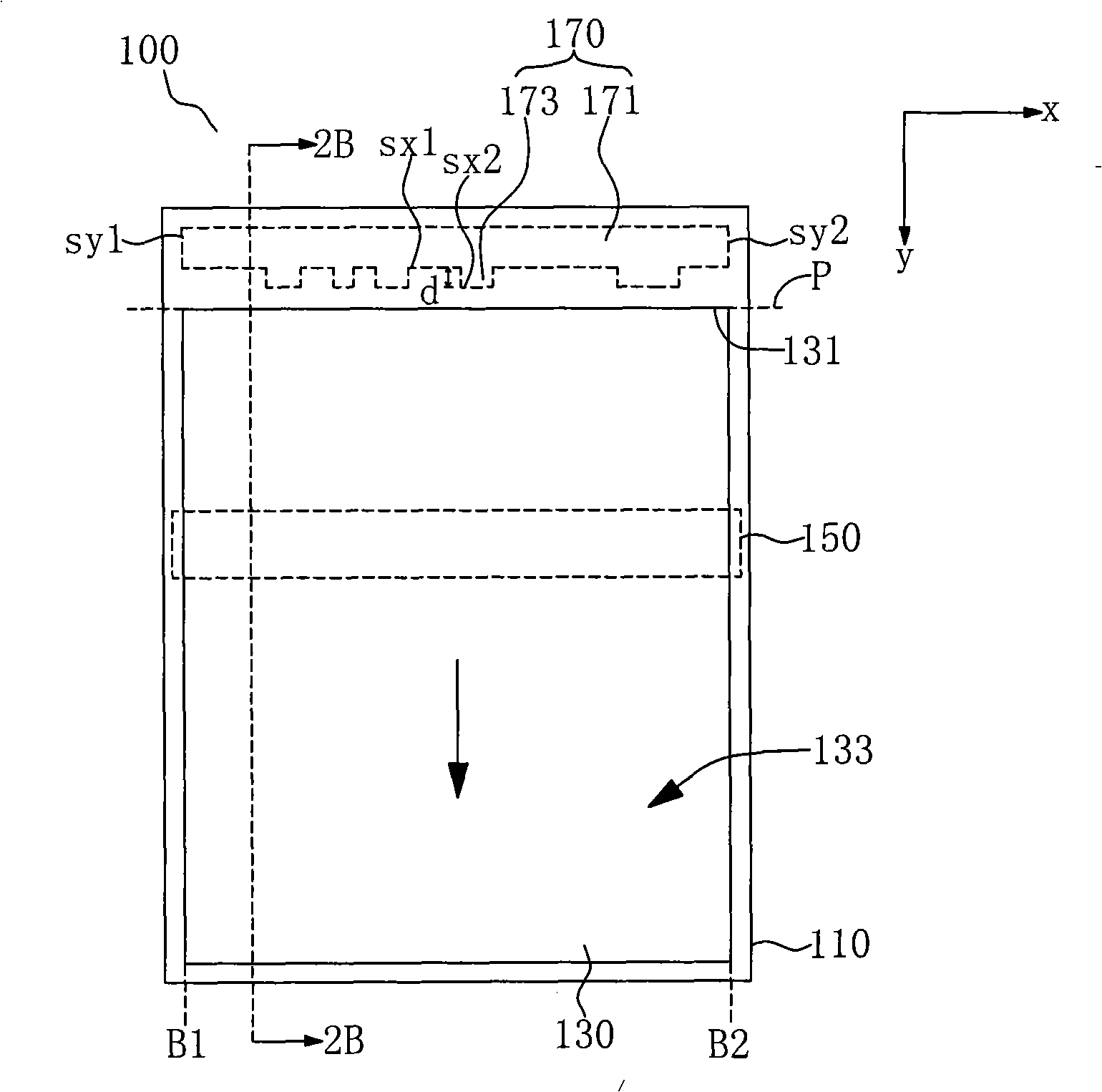
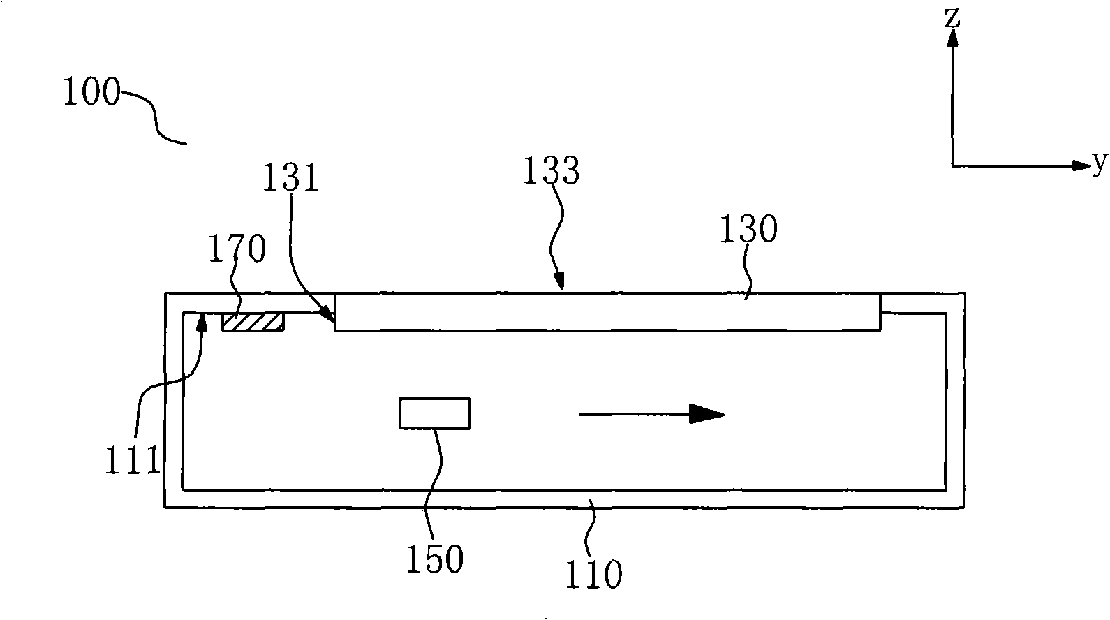
[0043] Example 1 please refer to Figure 2A and Figure 2B , the scanning device 100 includes a casing 110 , a scanning platform 130 , a scanning module 150 and a positioning plate 170 . The scanning module 150 may be a device including a Charge-Coupled Device (CCD) or a Contact Image Sensor (CIS).

[0044] The scanning platform 130 is embedded in the housing 110 and exposes a surface 133 for holding a document to be scanned (not shown). The scanning platform 130 includes an upper side 131 . The scanning module 150 is disposed under the scanning platform 130 . The positioning plate 170 is disposed on an inner wall 111 of the casing 110 and adjacent to the upper side 131 of the scanning platform 130 . The scanning module 150 is used to capture the images of the positioning plate 170 and the inner wall 111 of the housing 110, and identify an image corresponding to at least one side of the x-axis of the positioning plate 170. Here, the scanning module 150 identifies images co...

Embodiment 2

[0052] Example 2 please refer to Figure 3A and Figure 3B , the inner wall 111' of the casing 110' of the scanning device 100' has a notch 113'. Due to the concave design of the notch 113', the positioning plate 170' is accurately set in the notch 113'. In this way, the errors caused by the scanning module 150' in homing due to the offset of the positioning plate 170' can be reduced. Furthermore, the setting method of the positioning plate 170' can also be as follows: Figure 3A As shown, that is, the rectangular structure 173' protrudes from the main body 171' in the same direction as the rectangular structure 173 ( Figure 2A shown in ) from the subject 171 ( Figure 2A shown in ) protrude in different directions.

[0053] Also, please refer to Figure 4A and Figure 4B , the positioning plate 170" of the scanning device 100" may also have a plurality of square holes 175" ( Figure 4A label only one of the square holes). The square hole 175" runs through the positi...


PUM


Abstract

The invention provides a homing method for a scanning device and a scanning module thereof. A positioning plate of the scanning device is arranged on the inner wall of a shell; the scanning module indentifies at least one X axis side image corresponding to the positioning plate and determines a starting line for scanning according to the X axis side image. The homing method identifies at least one X axis side image corresponding to the positioning plate by capturing images between the positioning plate and the inner wall of the shell of the scanning device and determines the starting line of scanning according to the X axis side image and captures the image of a document to be scanned by moving along a Y axis direction from the starting line for scanning. The scanning module of the invention can accurately carry out homing and positioning, thus completely capturing the image of the document to be scanned and correspondingly improving the quality of the scanning. Meanwhile, a monochromic positioning plate can be adopted and the positioning plate does not need to set patterns in a manner of printing, therefore the cost and complexity of the production are lower than those of the traditional positioning structure, which is also beneficial for improving the facilitation and precision of the identification of the scanning module.

Description

technical field [0001] The invention belongs to a scanning device and a method for returning a scanning module thereof, and in particular relates to a scanning device capable of returning to a position and a method for returning a scanning module thereof. Background technique [0002] With the development of technology, the application of scanning devices is becoming more and more common. The scanning device generally includes a scanning platform and a scanning module. The scanning module is arranged under the scanning platform. When a user intends to scan a document, the document is placed on the scanning platform. The scanning module moves along a direction to capture the image of the document. [0003] Generally speaking, before scanning, the scanning module should be returned to a specific position to scan the document from a starting line. In this way, the scanning module can capture all the contents of the file. However, the scanning module may not be able to accu...

Claims


Application Information

Patent Timeline
Patent Type & Authority Applications(China)
IPC IPC(8): H04N1/04H04N1/047H04N1/10
Inventor 翁立奎占小兵
Owner QISDA SUZHOU
Why Eureka
Try Eureka