Rotary sound box for TV set

A technology for TVs and LCD TVs, which is applied in TVs, color TVs, and parts of color TVs. It can solve the problems of not being able to meet the needs of users to adjust sound effects, occupying space for speakers, and burdening them, so as to improve stereo effects and delays. effect of effect

Inactive Publication Date: 2008-10-01
MITAC COMP (SHUN DE) LTD +1
View PDF1 Cites 3 Cited by
  • Summary
  • Abstract
  • Description
  • Claims
  • Application Information

AI Technical Summary

Problems solved by technology

At present, most of the speakers and TV screens are integrated in one design, which cannot meet the needs of users to adjust the sound effect during use.
[0003] Another Chinese Taiwan Patent No. M289009 provides a TV structure with variable spatial configuration. This patent designs a separate sound box structure. It will also cause a burden during relocation and is easily damaged

Method used


Image

  • Rotary sound box for TV set
  • Rotary sound box for TV set
  • Rotary sound box for TV set

Examples


Embodiment Construction

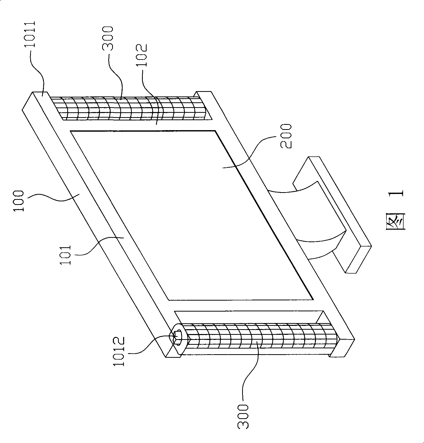
[0011] The following will take a liquid crystal television as an example to specifically illustrate the structure of the television rotary sound box of the present invention.

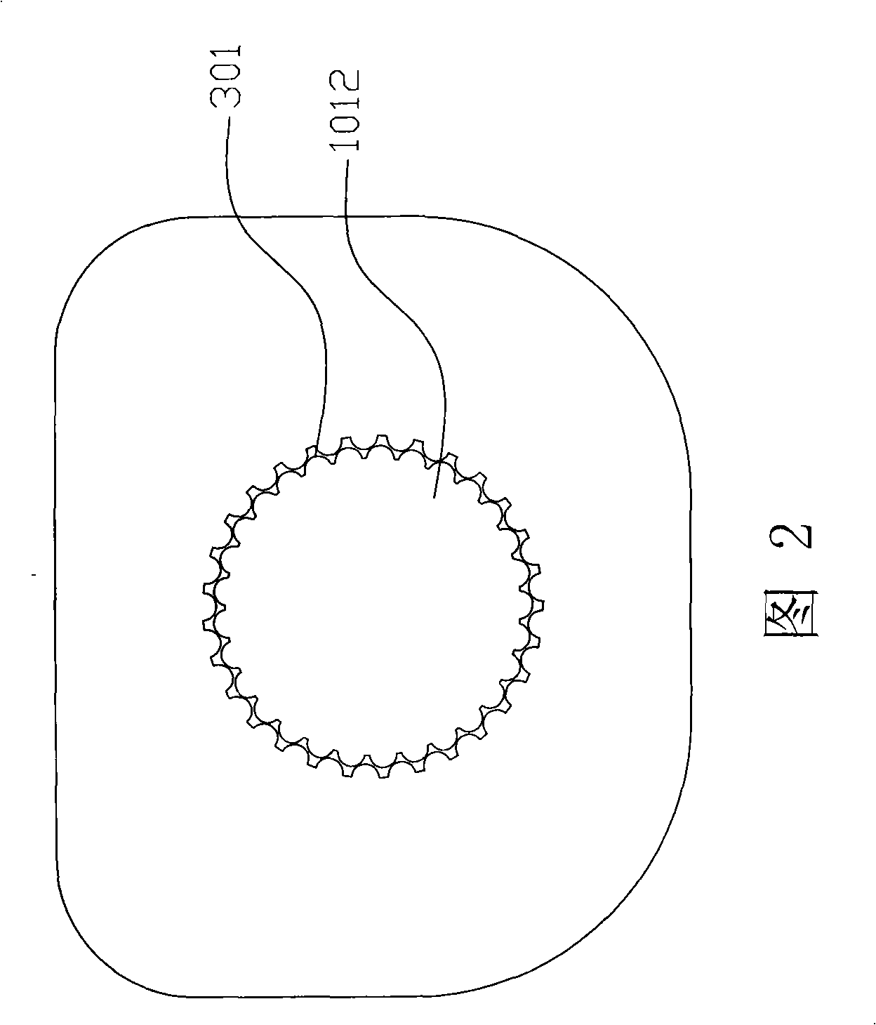
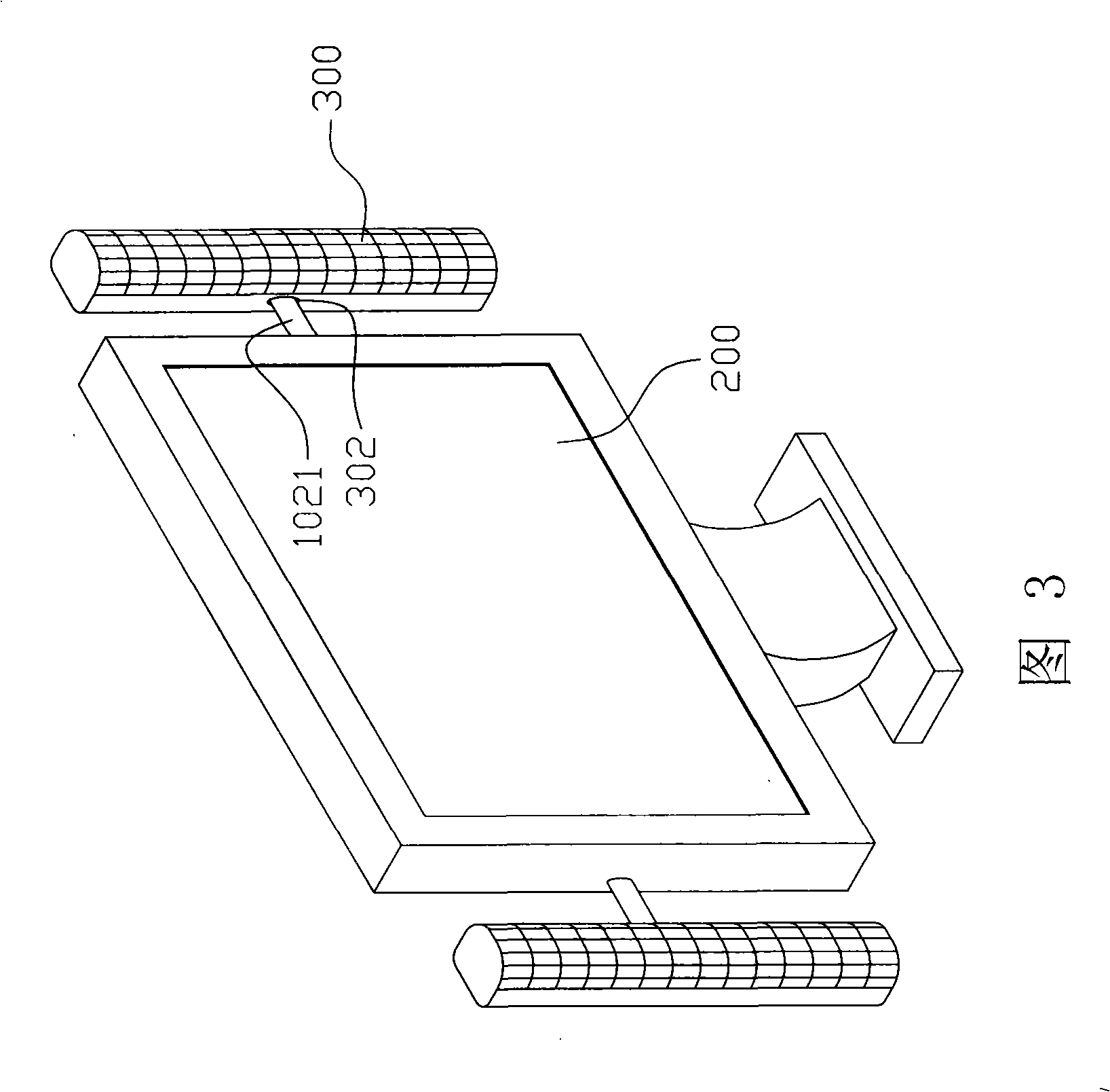
[0012] As shown in FIG. 1 , it is an overall schematic diagram of a TV rotary sound box provided by the present invention. As shown in the figure, its sound box 300 is to be respectively arranged on both sides of the fluorescent screen 200 of the TV body (not marked in the figure), and the fluorescent screen 200 is a rectangle, and the outer frame 100 of the fluorescent screen 200 is at least It includes four sides, and is specifically two long sides 101 parallel to each other and two short sides 102 perpendicular to the long sides, and wherein, the two long sides 101 extend outward along both ends for a certain length, and between the two long side extension ends 1011, a vertical shaft 1012 is respectively provided, and the above-mentioned sound box 300 is a cylinder shape, and its two ends are respect...


PUM


Abstract

The present invention provides a television rotation sound box, including at least two sound boxes mounted on the rotary shafts of the two sides of the television, and a rotary device is provided between the sound box and the rotary shaft to ensure the sound box surround the rotary shaft to an angle and locate, wherein, the rotary shaft is provided with a vertical shaft and a horizontal shaft, the sound box rotates around the vertical shaft from left to right or around the horizontal shaft up and down, and the maximum angle of the sound box rotation is depend on the length of electric wire connected between the sound box and the television body. Thus, the television rotation sound box of the invention ensures the sound box rotate to a certain angle and locates according to the user needs by the c the combination of the rotary shaft and the rotary device, thereby improving stereophonic effect and delay effect, acquiring sound effect of user hobby.

Description

technical field [0001] The invention relates to a TV sound box structure, in particular to a rotatable TV sound box structure. Background technique [0002] With the advancement of technology, people pay more and more attention to the quality and enjoyment of life, so the requirements for the effect of video media are getting higher and higher. However, the most basic equipment of video media equipment is speakers, so its design directly affects video media. the overall effect. At present, most of the speakers and the fluorescent screen of the TV are integrated in an integrated design, which cannot meet the needs of users to adjust the sound effect during use. [0003] Another Chinese Taiwan Patent No. M289009 provides a TV structure with variable spatial configuration. This patent designs a separate sound box structure. It will also cause a burden during relocation and be easily damaged. Therefore, the problems mentioned above also need to be improved. Contents of the ...

Claims


Application Information

Patent Timeline
Patent Type & Authority Applications(China)
IPC IPC(8): H04R1/02H04R1/20H04N5/64
Inventor 黄信嘉
Owner MITAC COMP (SHUN DE) LTD
Why Eureka
Try Eureka