CD ROM ball automatic balance system control method

A technology of automatic balance and control method, applied in the direction of rotational vibration suppression, poor vibration/sound insulation/absorption, recording of information on the disk, etc., can solve the problem that the ball cannot balance the vibration damping position, and cannot be applied

Active Publication Date: 2008-10-15
ASUSTEK COMPUTER INC
View PDF0 Cites 1 Cited by
  • Summary
  • Abstract
  • Description
  • Claims
  • Application Information

AI Technical Summary

Problems solved by technology

However, when optical drive manufacturers mass-produce optical drives, due to the different tolerances of each spindle motor in manufacturing, the ABS resonance point of each optical drive will be different, so the same set of spindle motor speed cont

Method used


Image

  • CD ROM ball automatic balance system control method
  • CD ROM ball automatic balance system control method
  • CD ROM ball automatic balance system control method

Examples


Embodiment Construction

[0018] Below in conjunction with accompanying drawing, structural principle and working principle of the present invention are specifically described:

[0019] As described above, the present invention provides a ball balancing method for a ball-type automatic balancing system for an optical drive. The details of the present invention will be further illustrated below by examples.

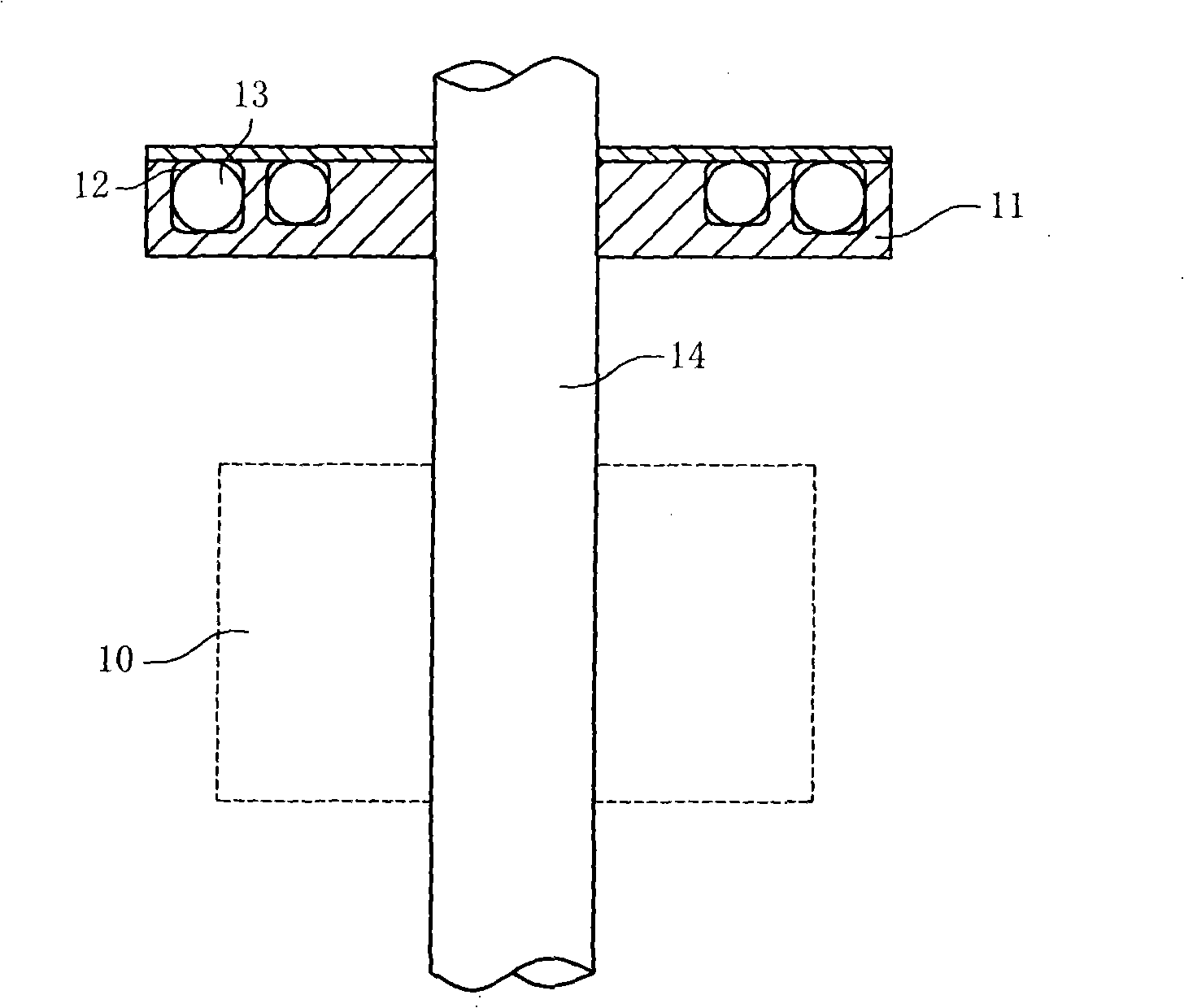
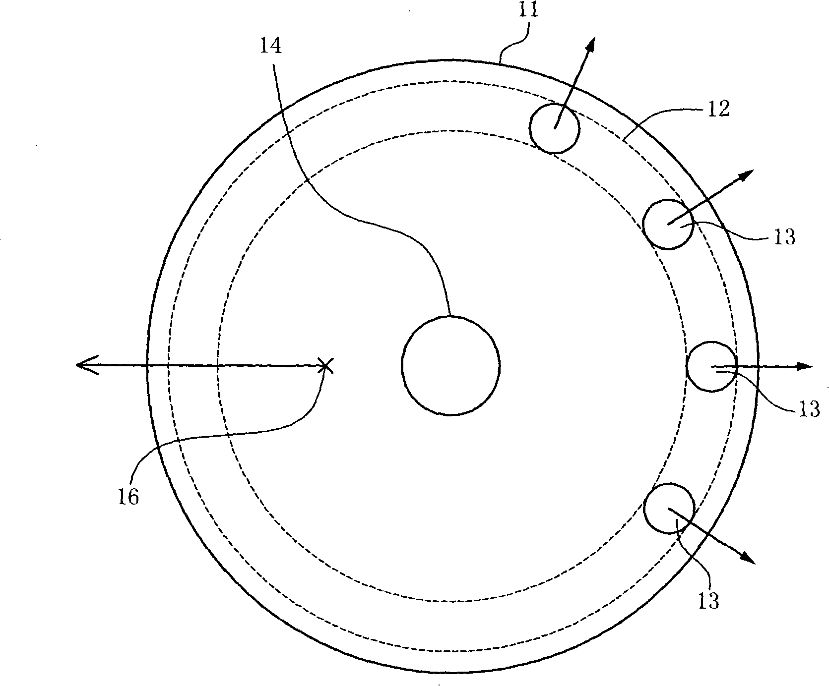
[0020] Please refer to figure 1 , which shows an automatic balancing system for an optical drive according to a preferred embodiment of the present invention. exist figure 1 Among them, the automatic balancing system of the optical drive includes: a spindle motor 10, a rotating body 11, and a rotating shaft 14, wherein the rotating body 11 includes at least one circular track 12 to accommodate balls 13 (such as steel balls).

[0021] The rotating body 11 is disposed above the spindle motor 10 , and the rotating body 11 can rotate synchronously with the spindle motor 10 . That is, the optical di...


PUM


Abstract

The invention discloses a control method used for a CD-ROM roller automatic balancing system. The method provides a rotary body which is fixed on the rotary shaft of the CD-ROM to lead the rotary body to revolve with the rotary shaft synchronously. Rollers are provided in a round rail in the rotary body to move smoothly. A revolution speed scope is arranged, and a main shaft motor drives the rotary shaft to accelerate-decelerate by at least two times within the revolution speed scope. During the multiple acceleration-deceleration of the main shaft motor, if a measured signal difference value is greater than the signal difference value measured previously, the acceleration-deceleration scope is adjusted. The roller balancing method of the roller-type automatic balancing system of the invention drives the rotary shaft to repeat the acceleration-deceleration within the revolution speed scope to further balance the rollers to the best vibration-reducing position in the round rail. Additionally, when the automatic balancing system generates a bigger difference caused by manufacturing tolerance, the acceleration-deceleration scope is adjusted again to be applied to all the CD-ROM automatic balancing systems.

Description

technical field [0001] The invention relates to an automatic ball balancing system of an optical drive, in particular to a control method for the automatic ball balancing system of an optical drive. Background technique [0002] With the rapid development of optical storage media, today's optical drives all take high-speed requirements as the development direction. The higher the read and write speed of the optical drive means that the optical drive can perform read and write functions when the spindle motor speed is higher. The higher the rotation speed, the greater the amount of vibration generated, and the center of gravity deviation caused by the imbalance of the optical disc itself will affect the stability of the optical drive to read the optical disc. [0003] In the actual use of high-speed optical drives, excessive vibration often causes the optical head to read the signal on the optical disc unstable, making it impossible for the optical drive to read and write op...

Claims


Application Information

Patent Timeline
IPC IPC(8): G11B19/20G11B33/08F16F15/14
Inventor 黄以民唐光华
Owner ASUSTEK COMPUTER INC
Why Eureka
Try Eureka