Front structure of automotive vehicle

A front body and automobile technology, applied to the upper structure, upper structure sub-assembly, vehicle parts, etc., can solve the problem of low collision load transmission efficiency, inability to fully restrain the cab, and low collision load transmission efficiency, which cannot fully suppress the rollover Issues such as movement ahead

Inactive Publication Date: 2008-10-29
MAZDA MOTOR CORP
View PDF1 Cites 15 Cited by
  • Summary
  • Abstract
  • Description
  • Claims
  • Application Information

AI Technical Summary

Problems solved by technology

[0005] In this conventional structure, when a frontal collision occurs to the vehicle and a rearward collision load is input to the vehicle body, as the collision load is shown by the dashed arrow in FIG. After the support tower installation position 96 is transferred to the gusset 99, it is first transferred to the outside in the vehicle width direction along the gusset 99, and then transferred to the hinge pillar 91 and the front pillar 97 through the fender upper member 98, so there is a collision. The problem that the load transfer efficiency is low and the movement of the cab (cabin) falling forward in the event of a frontal collision of the vehicle cannot be sufficiently suppressed
[0006] That is, when a vehicle collides head-on, the vehicle body falls forward and shifts, and if the transmission efficiency of the collision load is low as described above, it is difficult to efficiently distribute the load to the rear of the vehicle body, and the forward fall of the cab cannot be sufficiently suppressed. exercise

Method used


Image

  • Front structure of automotive vehicle
  • Front structure of automotive vehicle
  • Front structure of automotive vehicle

Examples


no. 1 Embodiment approach

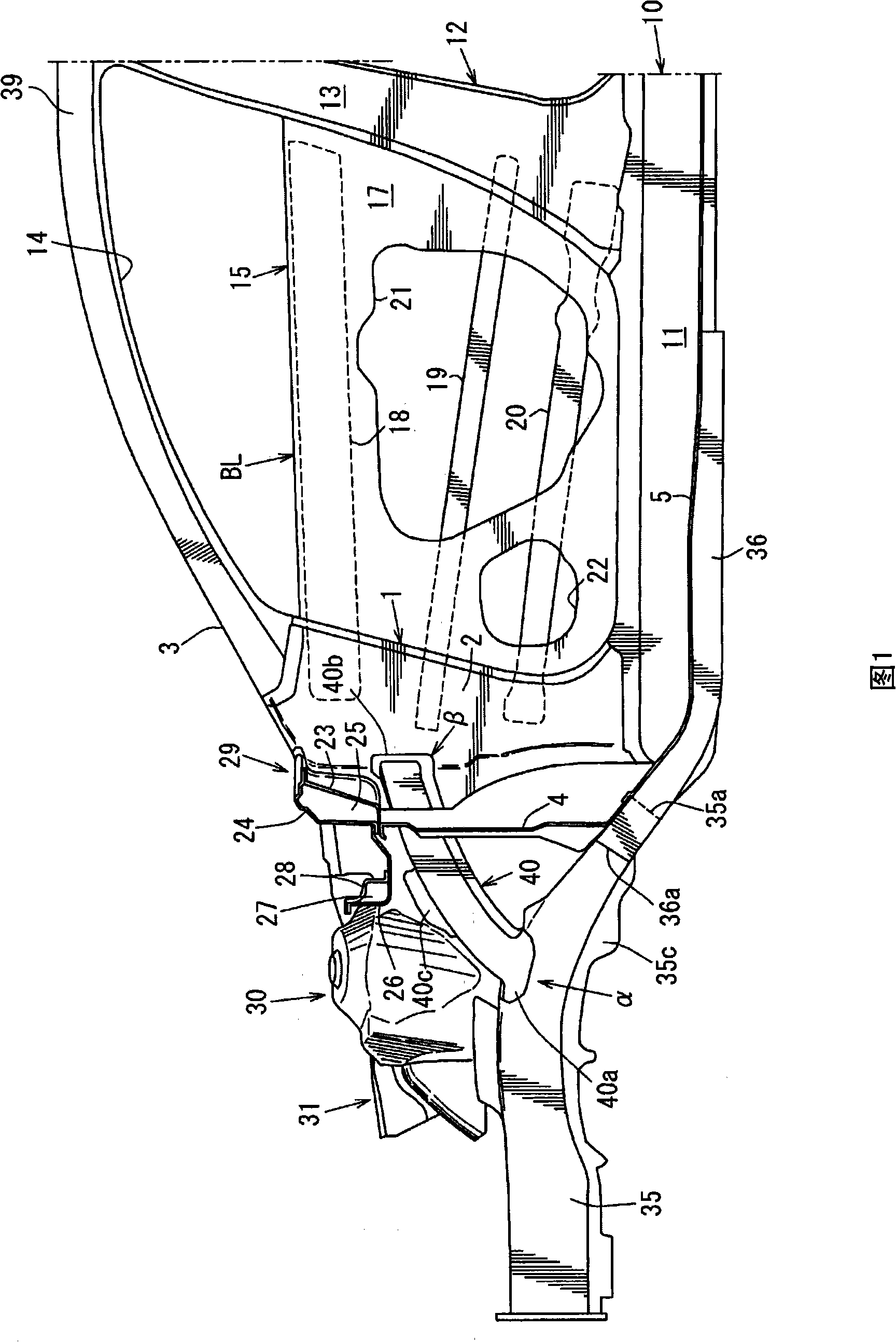
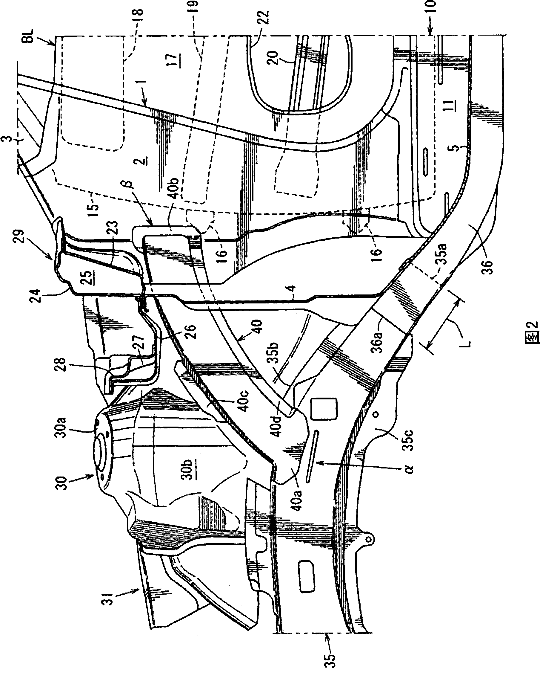
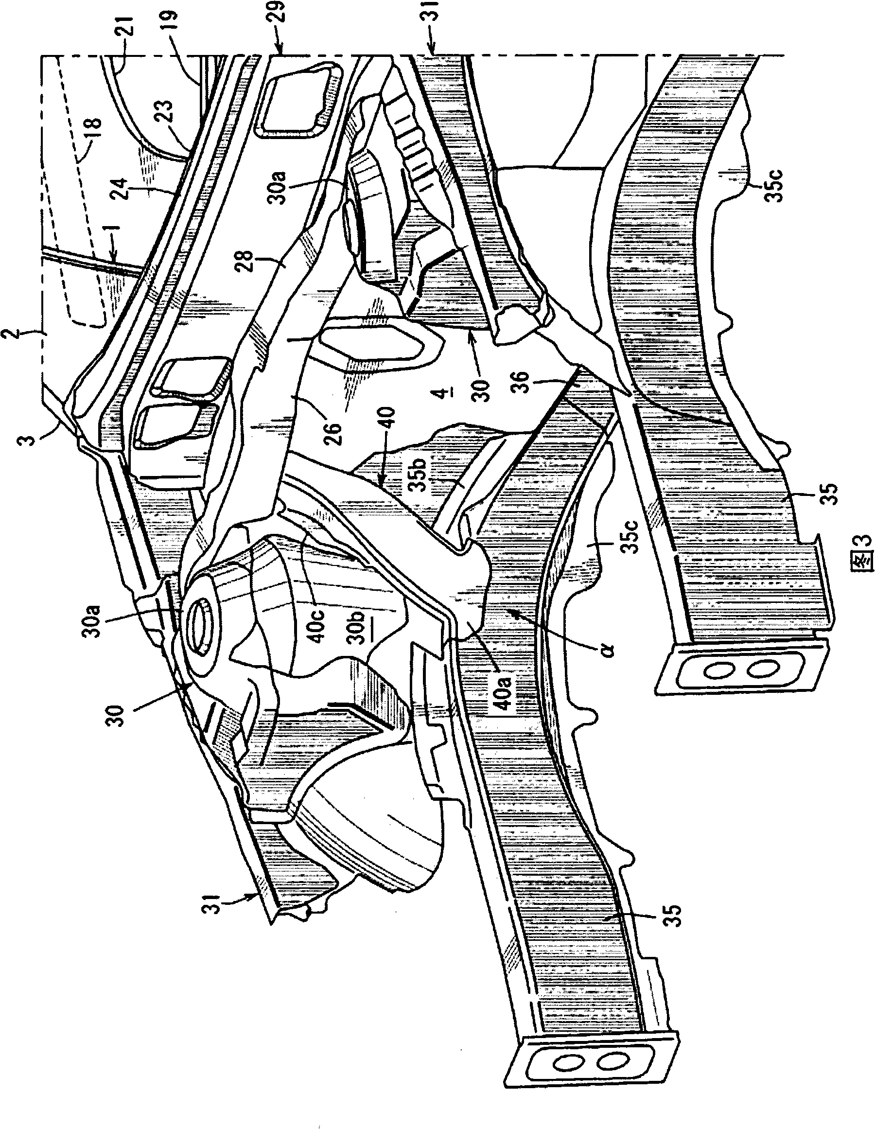
[0050] 1 is a side sectional view showing the front body structure of an automobile according to the first embodiment (a view of the front part of the vehicle body seen from the middle part in the vehicle width direction toward the outside in the vehicle width direction), and FIG. 2 is a main part of FIG. 1 Enlarged view, Fig. 3 is a perspective view of the main part of Fig. 1, and Fig. 4 is a state in which the cowl front panel 26 and the cowfront cross member 28 are removed, the structure of Fig. In the perspective view seen from above, Fig. 5 is a perspective view of the front body structure seen from the rear with the lower part 4 of the dash panel removed. Figure 6It is a sectional view along the arrow direction of the A-A line in Fig. 4, Fig. 7 is a sectional view along the arrow direction of the B-B line in Fig. 4, and Fig. 8 is a sectional view along the arrow direction of the C-C line in Fig. 4 .

[0051] The front body structure of the present embodiment includes a p...

no. 2 Embodiment approach

[0116] Hereinafter, the front body structure of the automobile according to the second embodiment of the present invention will be described with reference to FIGS. Figure 17 Be explained.

[0117] As shown in Fig. 12, in the automobile of this embodiment, the left and right ends of the dash panel 102 are respectively provided with hinge struts 103 (only one side is shown in the figure) extending in the vertical direction, and the hinge struts 103 are supported on the upper shaft. There are front doors.

[0118] The fender reinforcements 104 , 104 extend forward from the upper end sides of the left and right hinge struts 103 , respectively.

[0119] Front side members 105 , 105 extending substantially parallel to the apron reinforcements 104 , 104 in the front-rear direction of the vehicle body are provided at positions a certain distance inside of the apron reinforcements 104 , 104 in the vehicle width direction. Each front side member 105 is composed of an outer member an...


PUM


Abstract

A support frame is provided to extend upward and rearward from a portion of a front side frame near a suspension tower substantially straight and connect to an upper portion of a hinge pillar. Accordingly, there can be provided a front structure of an automotive vehicle that can properly restrain a forward deformation of a cabin by transmitting an impact load at a vehicle frontal crash to the hinge pillar efficiently.

Description

technical field [0001] The present invention relates to a front body structure of an automobile provided with a hinge strut, a dash panel, a suspension support tower and a front side member. Background technique [0002] Conventionally, as a front body structure of an automobile as described above, for example, there is a structure disclosed in Japanese Patent Application Laid-Open No. 2003-182633. [0003] That is, as shown in Figure 18, the structure includes a pair of left and right hinge pillars 91, 91 (only the structure on the right side of the vehicle is shown in Figure 18); 92 and the dashboard outside the figure separated by the vehicle compartment 93 at the rear; the suspension support tower 94 which is arranged at a certain distance in front of the vehicle of the dashboard; 94 is connected, and the rear end is bent downward to the front longitudinal beam 95 connected to the front of the floor beam outside the figure. In this structure, a gusset plate 99 as an aux...

Claims


Application Information

Patent Timeline
Patent Type & Authority Applications(China)
IPC IPC(8): B62D25/08
Inventor 清武真二木村隆之小桥正信松冈秀典寺田荣
Owner MAZDA MOTOR CORP
Why Eureka
Try Eureka