Micro-mechanical element capable of derivation

A micro-mechanical and component technology, applied in the field of deflectable micro-mechanical components, can solve the problems of spring nonlinear characteristics, insufficient stiffness, high cost, etc.

Active Publication Date: 2008-12-03
FRAUNHOFER GESELLSCHAFT ZUR FOERDERUNG DER ANGEWANDTEN FORSCHUNG EV
View PDF0 Cites 21 Cited by
  • Summary
  • Abstract
  • Description
  • Claims
  • Application Information

AI Technical Summary

Problems solved by technology

[0008] However, all these known solutions have disadvantages
These disadvantages relate to higher construction and manufacturing effort and / or expense, insufficient stiffness in certain axial or torsional moments, and undesired non-linearity of the spring characteristics

Method used


Image

  • Micro-mechanical element capable of derivation
  • Micro-mechanical element capable of derivation
  • Micro-mechanical element capable of derivation

Examples


Embodiment Construction

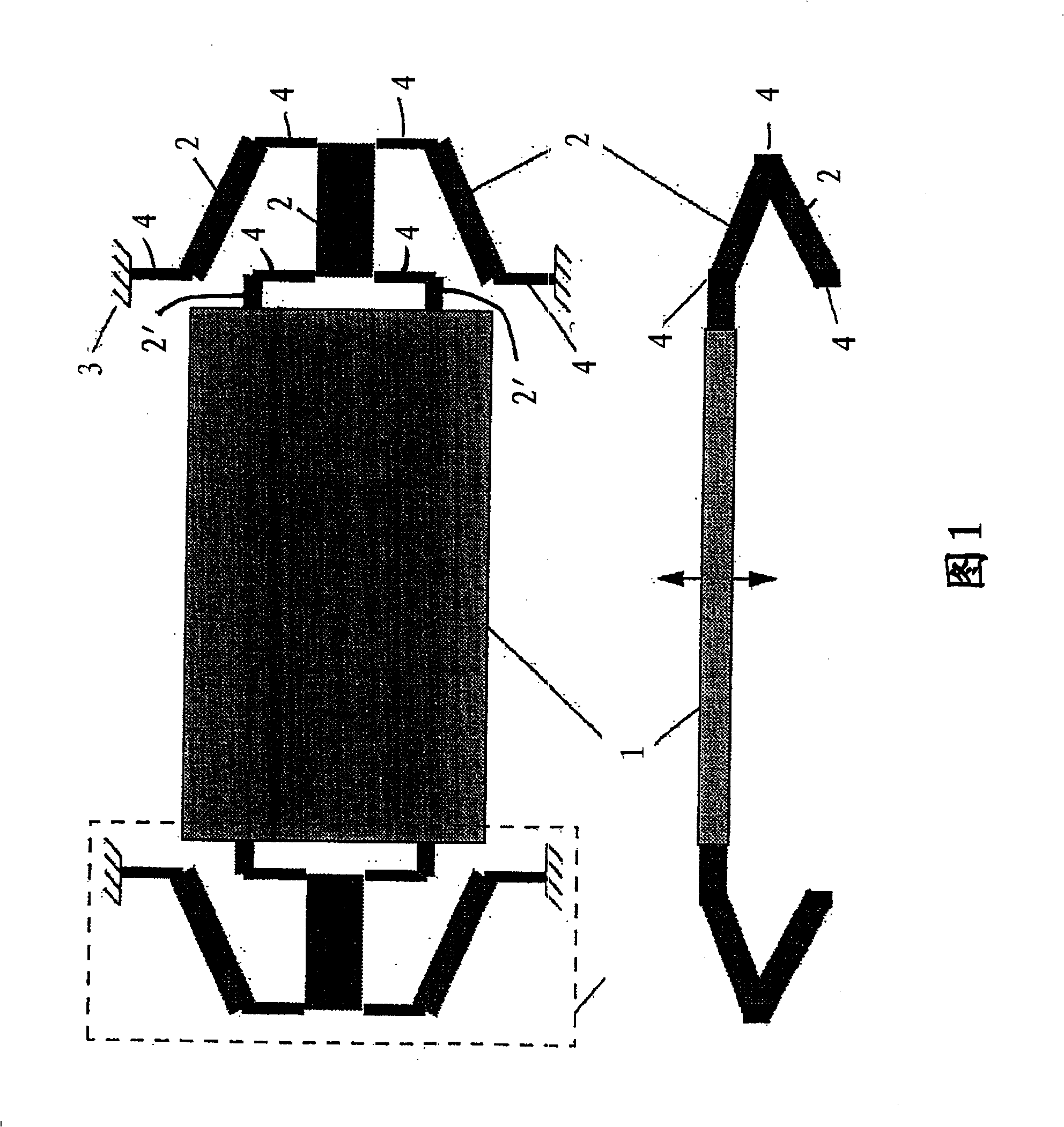
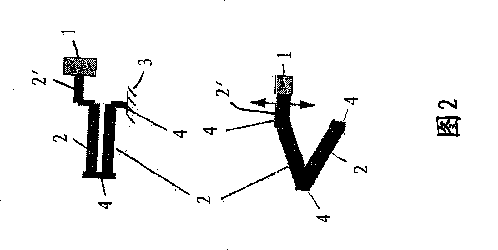
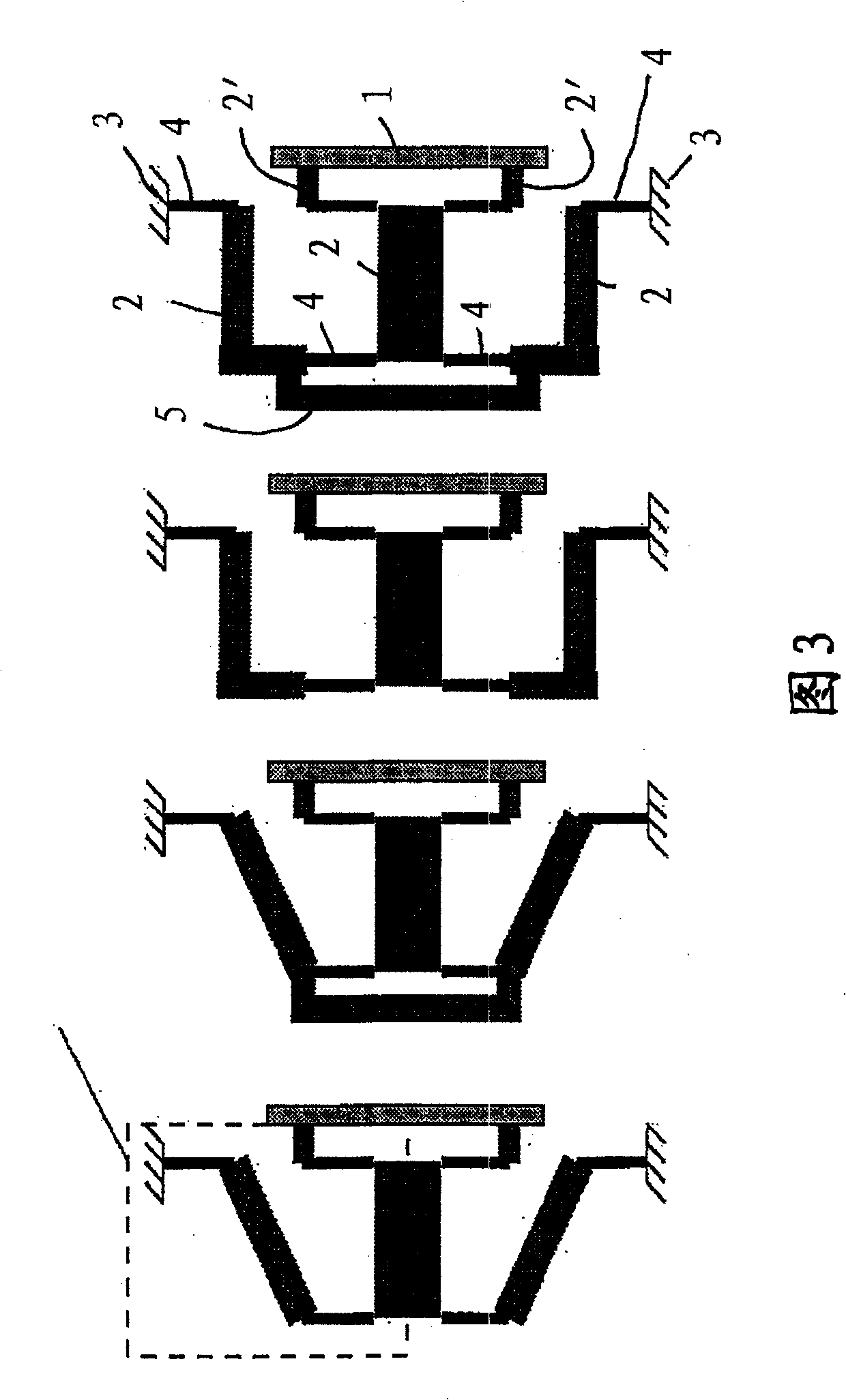
[0042] An exemplary embodiment of an element according to the invention is shown in two views in FIG. 1 . In the plan view shown at the top, it is clearly seen that the suspension of the micromechanical element 1 is formed with two spring systems arranged diametrically opposite at the micromechanical element 1 and joined to the micromechanical element 1 by means of a connecting rod 2'. mechanical element 1. On one side of the link 2, the link 2' is pivotally connected to the link 2 by means of a torsion spring element 4. At the other side of the connecting rod 2 two torsion spring elements 4 in turn connect the connecting rod 2 with two other corresponding connecting rods 2 in a pivotal connection. The latter so-called connecting rod 2 is inclined at an oblique angle relative to the axis of the torsion spring element 4 . At the other end of the connecting rods 2 there is again a torsion spring element 4 which is connected to the end faces of the connecting rods 2 on one...


PUM


Abstract

The invention relates to micromechanical elements which can be deflected, and which can preferably be deflected translationally, and possibly also in an oscillatory form. In comparison to known solutions, the object of the invention is to allow larger deflections, with better resistance at the same time to side forces and torques. In this case, suspension by at least one spring system is provided on elements according to the invention. Levers which are connected in an articulated manner to torsion spring elements are provided on spring systems. Torsion spring elements of a spring system are aligned on a common axis and / or on a plurality of axes which are aligned parallel to one another, and at least one torsion spring element is firmly clamped in.

Description

technical field [0001] The invention relates to a deflectable micromechanical element. In this respect, the deflection can take place in translation along the axis, but also by pivoting about the axis. In translational deflection, in particular, the respective axis is aligned perpendicular to the plane of the micromechanical element. Deflection can also occur in the form of vibrations. Drive concepts known per se, for example electrostatic drive concepts, can be used for this deflection. Background technique [0002] For the last-mentioned element, also called the translational oscillator, the translational oscillator is suspended on a spring and should not tilt during translational deflection. Straight bent springs or folded bent springs can be used with this spring. In this regard, the stiffness against lateral forces, resistance to tension and torque should be high. In contrast, it is desirable to use springs that are relatively soft in the direction of deflection. ...

Claims


Application Information

Patent Timeline
Patent Type & Authority Applications(China)
IPC IPC(8): B81B3/00
CPCG02B26/08B81B3/0062
Inventor 亚历山大·沃尔特托马斯·克洛泽
Owner FRAUNHOFER GESELLSCHAFT ZUR FOERDERUNG DER ANGEWANDTEN FORSCHUNG EV
Why Eureka
Try Eureka