Check patentability & draft patents in minutes with Patsnap Eureka AI!

Epicyclic reduction gear with multiple modular stages

A technology of planetary reduction and reduction gears, applied in the direction of gear transmissions, belts/chains/gears, building components, etc.

Inactive Publication Date: 2012-07-04
GAPOSA
View PDF0 Cites 0 Cited by
  • Summary
  • Abstract
  • Description
  • Claims
  • Application Information

AI Technical Summary

Problems solved by technology

[0010] Another disadvantage of the known technology is manifested in the fact that the production requirements for the different reduction stages selectively used in the planetary reduction gear stage gear train, relative to the torque or speed obtained at the output of the tubular electric motor reducer The reduction stage is selected

Method used


Image

  • Epicyclic reduction gear with multiple modular stages
  • Epicyclic reduction gear with multiple modular stages
  • Epicyclic reduction gear with multiple modular stages

Examples


Embodiment Construction

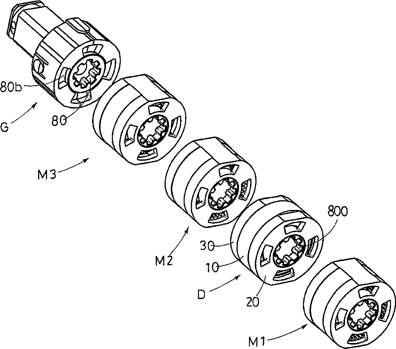
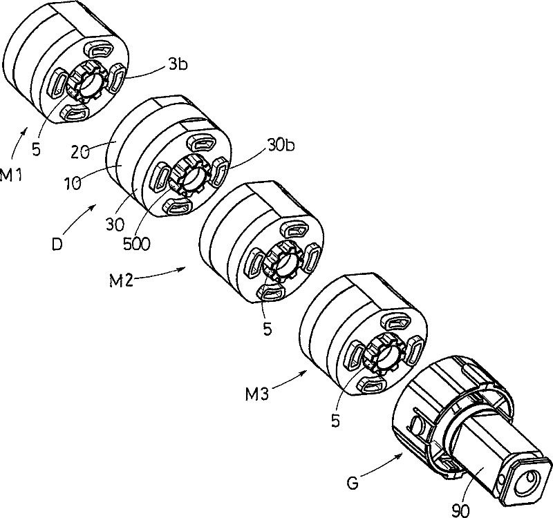
[0022] It must be noted that the accompanying figures show a planetary reduction gear formed by three combined stages, each stage having an "inner" mesh at the input and an "outer" mesh at the output. Obviously, it is also possible to equip the input side with the internal snap-in device and the output side with the external snap-in device.

[0023] refer to figure 1 with figure 2 , the planetary reduction gear R is formed by a gear train of three combined reduction stages M1, M2, M3, which are designed to be connected one after the other in any order.

[0024] M1 represents the first reduction stage, that is, the reduction stage toward the motor (not shown in the figure), and M3 represents the last reduction stage, that is, the reduction stage toward the winding roller of the roller blind (not shown in the figure). .

[0025] The reduction stages M1, M2, M3 have the same size and construction, while the gear ratio depends on the size of the gears they contain.

[0026] r...


PUM


Abstract

The present invention relates to an epicyclic reduction gear with multiple modular stages for tubular motor reducers operating winding roller shutters, roller shades and the like, which is formed of a train of multiple modular stages (M1, M2, M3) designed to be coupled one after the other. The epicyclic reduction gear ?with multiple modular stages is characterized in that each reduction stage is provided with a hub (8) with internal teeth (8b) at the center of one side, and provided with a pin (5) engaging with the internal teeth (8b) of adjacent reduction stage at the other side, and the pin (5) of each reduction stage is coupled to the hub (8) with the internal teeth (8b) of the adjacent reduction stage.

Description

technical field [0001] The invention relates to a multi-stage combined planetary reduction gear for a tubular motor reducer used for winding a roller blind, a roller curtain, etc. Background technique [0002] The structural form and operation mode of the tubular motor reducer are standardized. [0003] This type of motor reducer includes a multi-stage combined planetary reduction gear housed in a tubular housing, driven to rotate by an electric motor mounted on an external position of one of the two openings of the tubular housing, and in the following manner Orientation: so that its axis is aligned coaxially with said tubular casing and the pin of the last stage protrudes from the opposite opening for the power take-off. [0004] An adapter directly connected to the roller screen shaft is splined on said pin. [0005] A motor reducer of this type is disclosed in European Patent No. 976909 of the same applicant. [0006] Usually, said planetary reduction gear consists of...

Claims


Application Information

Patent Timeline
Patent Type & Authority Patents(China)
IPC IPC(8): E06B9/72E06B9/68
CPCF16H1/46E06B2009/725E06B9/68
Inventor 保罗·加斯帕里尼丹特·波斯塔基尼
Owner GAPOSA
Features
  • R&D
  • Intellectual Property
  • Life Sciences
  • Materials
  • Tech Scout
  • Unparalleled Data Quality
  • Higher Quality Content
  • 60% Fewer Hallucinations
Learn More