Self-retracting lanyard and braking mechanism with pawl lockout

A braking mechanism and pawl technology, applied in safety belts, building rescue, life-saving equipment, etc.

Inactive Publication Date: 2009-04-08
MSA TECH
View PDF7 Cites 9 Cited by
  • Summary
  • Abstract
  • Description
  • Claims
  • Application Information

AI Technical Summary

Problems solved by technology

However, none of these devices has addressed the rope rebound suppression to the same extent as the present invention

Method used


Image

  • Self-retracting lanyard and braking mechanism with pawl lockout
  • Self-retracting lanyard and braking mechanism with pawl lockout
  • Self-retracting lanyard and braking mechanism with pawl lockout

Examples


Embodiment Construction

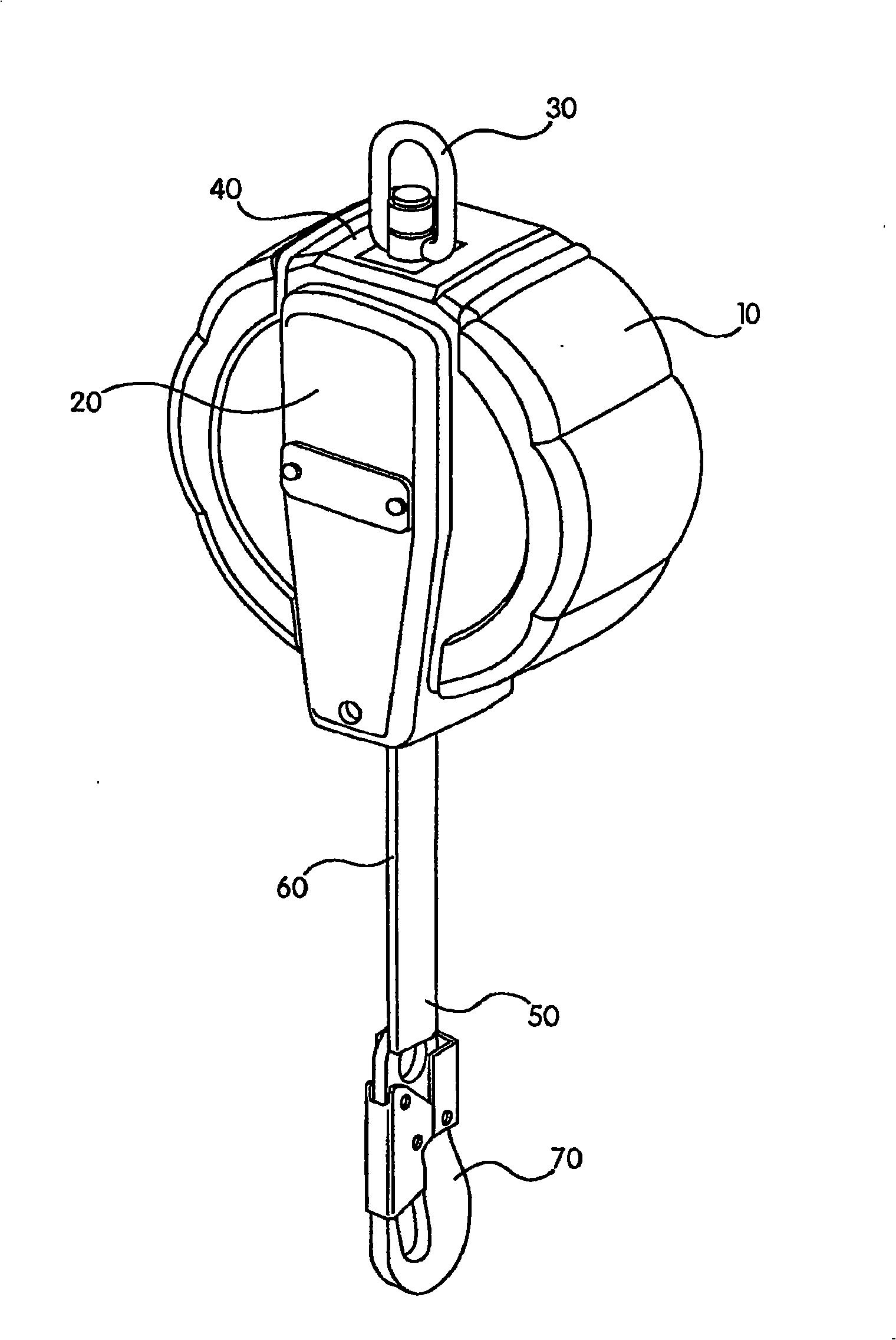
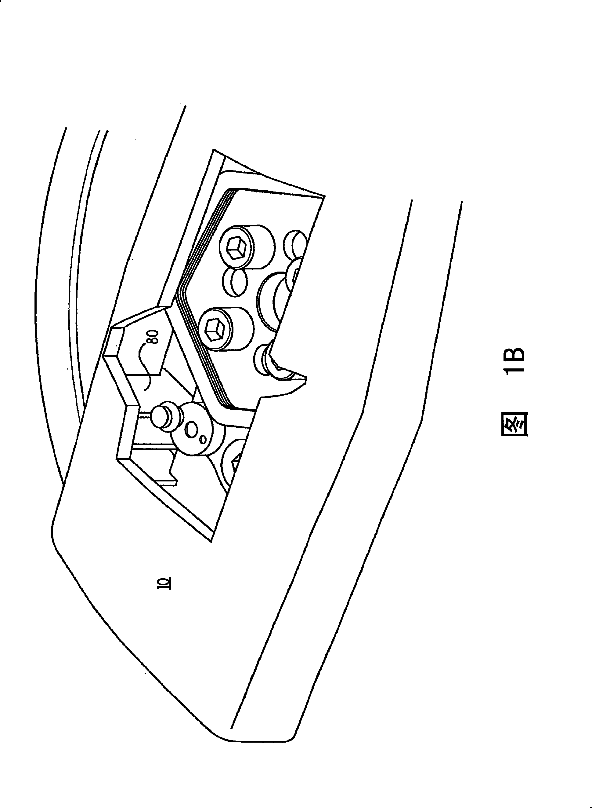
[0021] see now Figure 1A , showing a fully assembled typical self-retracting guy line. The improved braking mechanism of the present invention with pawl locking elements is located inside the SRL unit and cannot be seen in this figure. However, the brake mechanism portion is better shown in the exploded partial cutaway view of FIG. 1B . This SRL comprises a casing 10 around which is covered a cover 20 which is removable for maintenance. The housing 10 is at one end (in terms of direction, at Figure 1A top) has a fixation connector 30 for enabling the SRL wearer / user to fix the unit to a fixation point. In this particular model, a load indicator button 40 is also shown to quickly indicate that this particular unit has not been subjected to drop arrest and is thus presently safe to use.

[0022] exist Figure 1A Below the casing 10, extends the rope 50, in this case, the rope is made of nylon straps, but it is also understood that the braking mechanism of the present inve...


PUM


Abstract

A self-retracting lanyard having a housing; a rotatable drum in that housing; a line for winding about that drum; and an improved braking mechanism for preventing the -drum in that housing from ratcheting due to line rebounding after a fall arrest event. The braking mechanism has a plurality of pawl lockout elements for flexibly engaging with a stationary component of the lanyard to keep at least one pawl in a locked position during reverse rotation of the drum thereby preventing ratcheting from occurring.

Description

[0001] Cross References to Related Applications [0002] This application claims the benefit of US Provisional Patent Application Serial No. 60 / 782,053, filed March 16, 2006, the contents of which are incorporated herein by reference. technical field [0003] The present invention relates to a self retracting lanyard or "SRL" which is primarily intended for industrial use, but is also suitable for some recreational use. The invention also relates to a larger range of controlled fall devices, especially for use with harnesses to protect their wearers from sudden accelerated fall arrest events. Background technique [0004] Self retracting guy wires have a variety of industrial end uses including but not limited to: construction, fabrication, hazardous materials / remediation, asbestos abatement, painting, sandblasting, welding, mining, various oil and gas industry applications, power utilities, nuclear energy, pulp and paper , sanding, grinding, multi-stage rigging, roofing, ...

Claims


Application Information

Patent Timeline
Patent Type & Authority Applications(China)
IPC IPC(8): A62B35/04
CPCA62B1/08A62B35/0093
Inventor T·W·埃克
Owner MSA TECH
Why Eureka
Try Eureka