Slice material conveying device and image forming device

A material conveying device and sheet technology, applied in thin material processing, transportation and packaging, electrical recording technology using charge graphics, etc., can solve problems such as insufficient conveying force, bearing deviation, and inability to obtain pressure

Inactive Publication Date: 2009-06-03
RICOH KK
View PDF1 Cites 10 Cited by
  • Summary
  • Abstract
  • Description
  • Claims
  • Application Information

AI Technical Summary

Problems solved by technology

That is, the problem that the reverse curl cannot be applied to the transfer paper S, or the problem of paper jams due to insufficient conveying force applied to the transfer paper S
In addition, if a spring with a high spring constant is used as the elastic member 77, it is expected that the anti-curl function can play a role when the ultra-thick paper is conveyed. A driven roller constantly exerts a strong pressure on the ejection roller 62. For this reason, the fixing member for fixing the elastic member 77 and the rotation shaft of the ejection roller 62 are deformed in a direction apart from each other, so that the elastic member 77 becomes stretched and cannot obtain the expected pressure
Therefore, due to the strength of the transfer paper S when conveying ultra-thick paper, the stick support 78 is pressed down, and it is impossible to improve the anti-curling effect on ultra-thick paper.
Furthermore, if the rotation shaft of the paper discharge roller 62 is deformed, the driving force may increase or the bearing may deviate and be damaged.

Method used


Image

  • Slice material conveying device and image forming device
  • Slice material conveying device and image forming device
  • Slice material conveying device and image forming device

Examples


Embodiment Construction

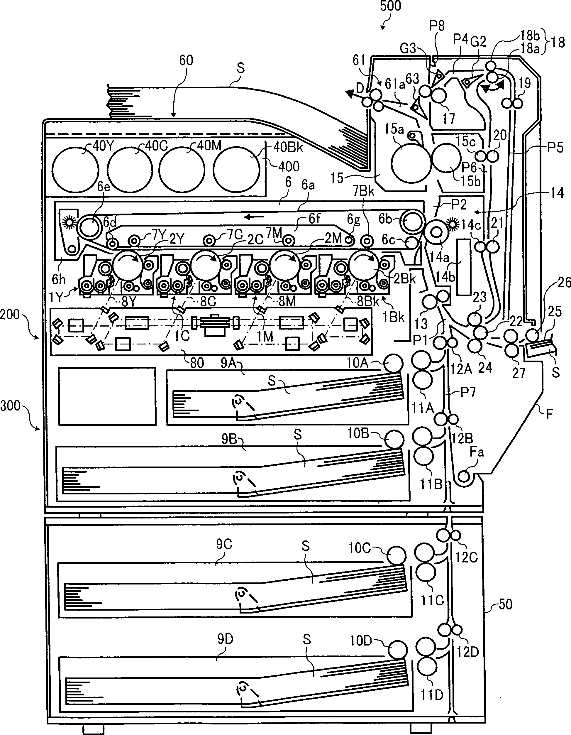
[0052] Hereinafter, a line type color laser printer (hereinafter simply referred to as printer 500 ) in which a plurality of photoreceptors are arranged in parallel will be described as an example of an image forming apparatus to which the present invention is applied.

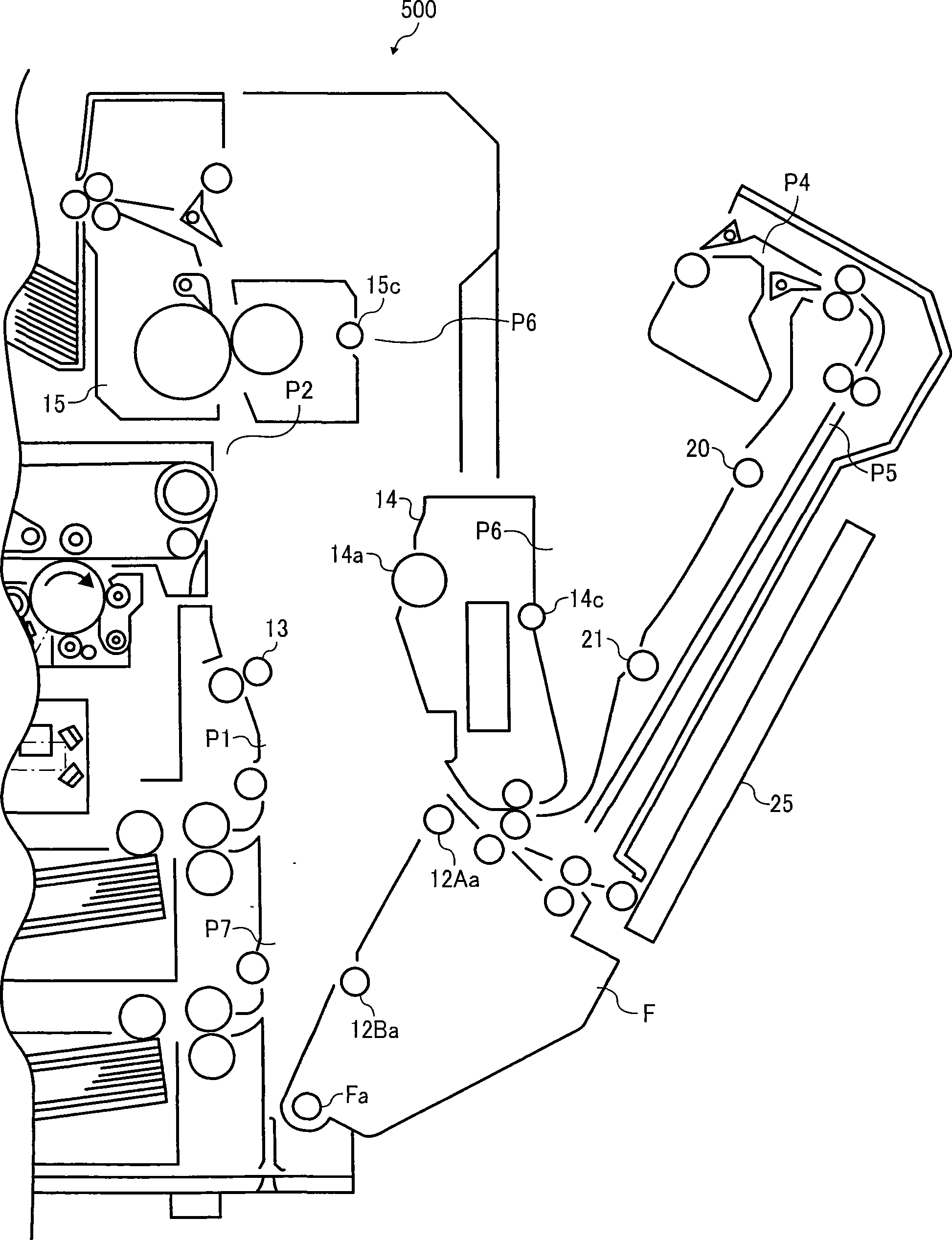
[0053] figure 1 It is a schematic structural diagram of the printer 500 according to this embodiment. The printer 500 includes an image forming unit 200 , a paper feeding unit 300 on which the image forming unit 200 is placed, and the like.

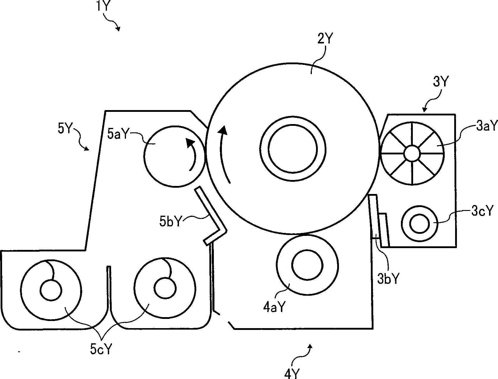
[0054] Inside the device of the printer 500, four image forming units 1 (Y, C, M, Bk) are provided as image forming devices for forming yellow (Y), cyan (C), magenta (M), black (Bk) Various images. The image forming section 1 (Y, C, M, Bk) includes drum-shaped photoreceptors 2 (Y, C, M, Bk) respectively, and the four photoreceptors 2 (Y, C, M, Bk) are formed in the image forming section. 200 are arranged side by side at the same interval. When the printer 500 operates...


PUM


Abstract

The present invention relates to a slice material conveying device and an image forming device, the aim is to provide a slice material conveying device capable of playing a function of coiling and rectification through thick paper between rollers without addition of contact pressure applied by a driven roller to a drive roller. The device includes an inverse coiling part (600) having a paper-discharging roller (62), rotating actively along the conveying direction of the slice material; two coiling rectification rollers (65, 66), contacting the paper-discharging roller (62) separately to rotate drivenly; two holding bodies (68, 69), supporting the two coiling rectification rollers (65, 66) to move freely to change the span with the paper-discharging roller (62); two elastic members (70, 71), applying active force to the holding body separately to make the coiling rectification rollers to access the paper-discharging roller (62), characterized in that the coiling part is also provided with a limit part (90), for limiting the span between the coiling rectification rollers and the paper-discharging roller (62) to be less than a thick value of the most thick slice material.

Description

technical field [0001] The present invention relates to a sheet conveying device used in image forming devices such as electrophotographic copiers, laser printers, and facsimile devices, and to an image forming device including the sheet conveying device. Background technique [0002] In the prior art, there is a paper discharge device as the above-mentioned sheet material conveying device for forming an unfixed image on the surface through an image forming unit, and transferring the unfixed image after being fixed by a fixing device, etc. The sheet-like recording medium is ejected from the fixing device to the outside of the image forming device. [0003] Figure 15 An example of the output unit is shown. The paper discharge device 61 shown in this figure includes a guide member 61a, a paper discharge roller 62 driven by a driving source not shown in the figure to actively rotate, and a paper discharge roller 62 that is in contact with the paper discharge roller 62 and dri...

Claims


Application Information

Patent Timeline
Patent Type & Authority Applications(China)
IPC IPC(8): B65H29/20B65H29/70G03G15/00
Inventor 青野芳大
Owner RICOH KK
Why Eureka
Try Eureka