Rotary type electric component

An electrical component, rotary technology, applied in electrical components, circuits, electrical switches, etc., to solve problems such as reduced "click" feeling, difficulty in obtaining a sense of joint, and durability of leaf springs

Inactive Publication Date: 2009-06-10
ALPS ALPINE CO LTD
View PDF1 Cites 5 Cited by
  • Summary
  • Abstract
  • Description
  • Claims
  • Application Information

AI Technical Summary

Problems solved by technology

[0007] However, in the above-mentioned conventional rotary electric component, the "click" feeling when the shaft 390 is rotated is obtained by the concave-convex portion 300e provided on the back surface of the mounting base 300 and the convex...

Method used


Image

  • Rotary type electric component
  • Rotary type electric component
  • Rotary type electric component

Examples


Embodiment Construction

[0036] Hereinafter, embodiments of the present invention will be described in detail with reference to the drawings. In this embodiment, an encoder switch is exemplified as a rotary electric component, but a varistor which is one type of rotary electric component can also be applied.

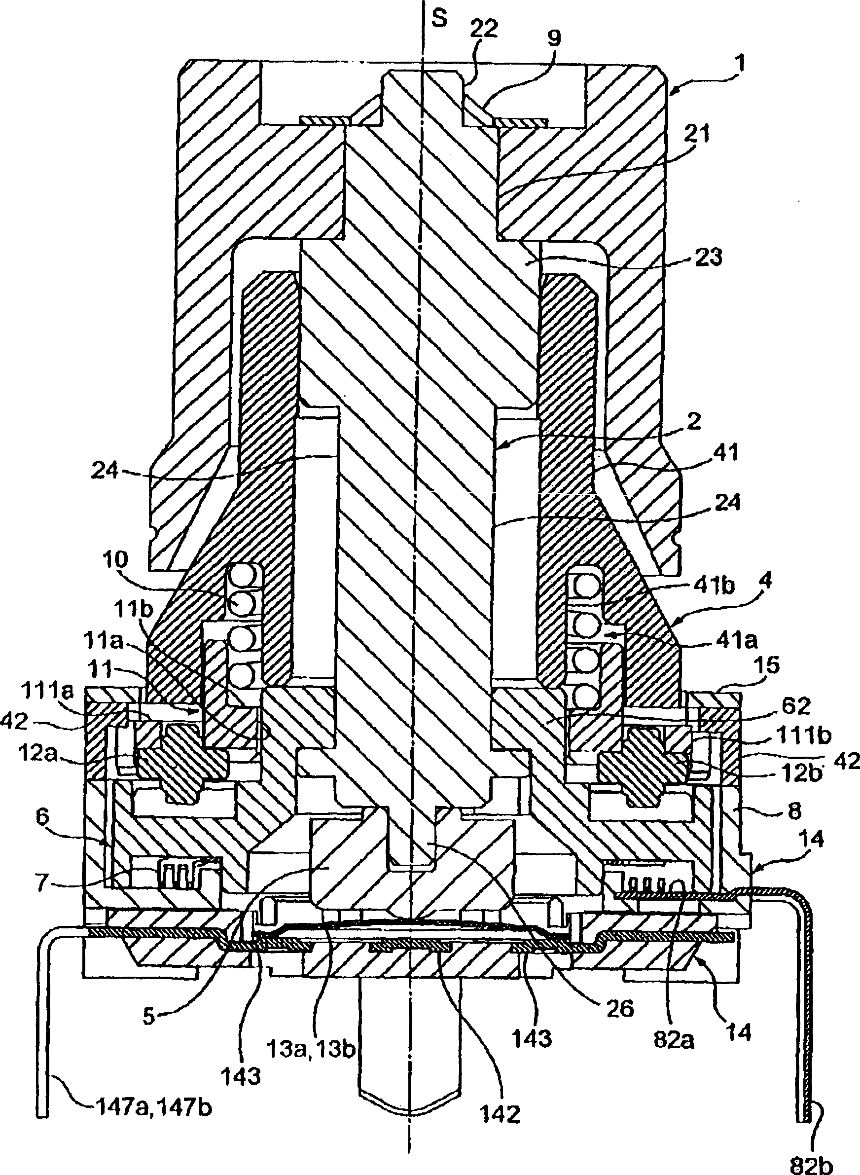
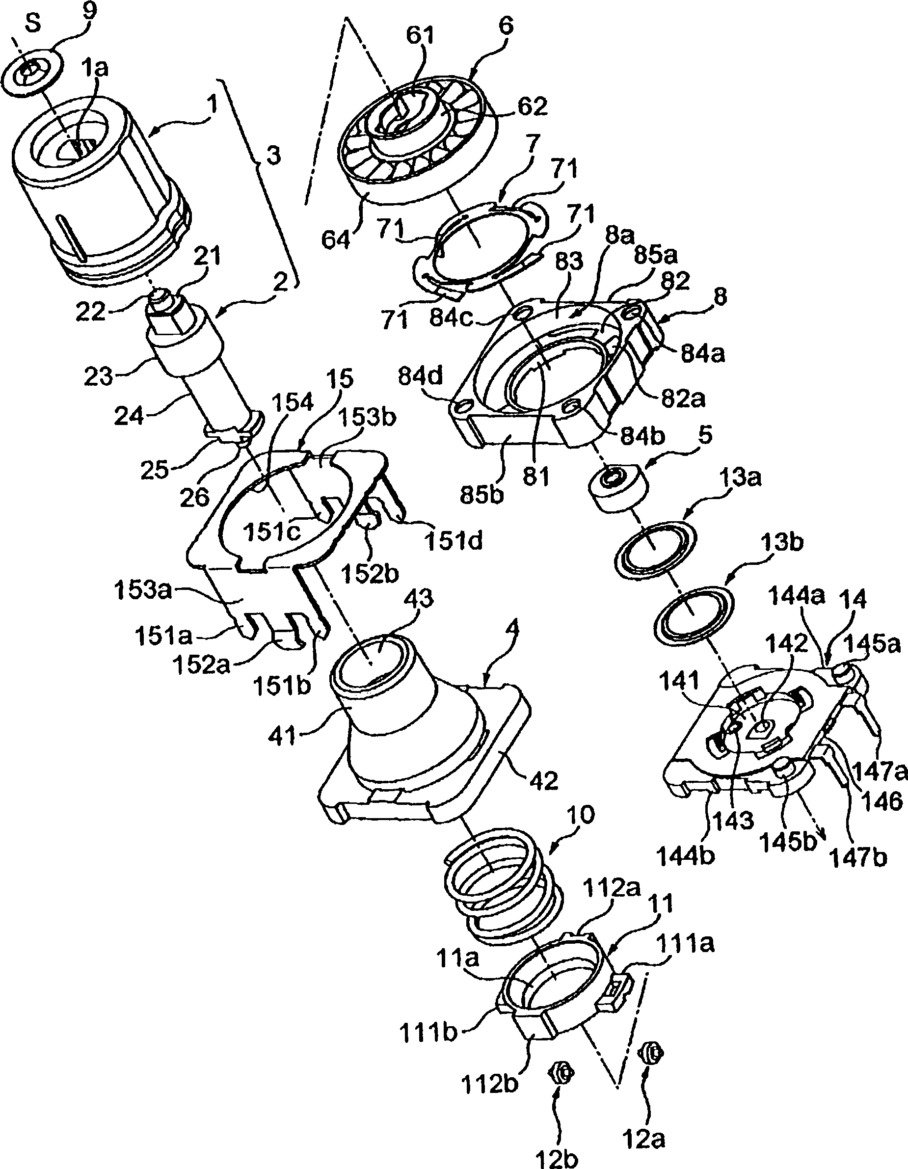
[0037] figure 1 It is a cross-sectional view of a rotary electric component according to an embodiment of the present invention, figure 2 It is an exploded perspective view of the rotary electric component of this embodiment. The operation shaft 3 constituted by the outer shaft 1 and the inner shaft 2 can be supported by a bearing member for rotation and pressing operation. The pressing member 5 is press-fitted and fixed to one end of the inner shaft 2 inserted into the rear side of the bearing member 4 . On the rear surface (the other side) of the rotary member 6 is fixed a sliding member 7 made of an annular metal plate as a sliding contact. The rotating member 6 is held rotatably in a r...


PUM


Abstract

In a rotary type electric component, a click mechanism is composed of a coil spring (10); a holding member (11), which holds the coil spring (10) by being held by a bearing member (4) not to be rotated and has two rollers (12a, 12b) having a direction orthogonally intersecting with an axial line (S) as a rotating axis; and a rotating member (6) having a click engaging section (64) with which the two rollers (12a, 12b) of the holding member (11) engage and disengage. The click mechanism rolls while the two rollers (12a, 12b) of the holding member (11) engage and disengage with an uneven section (66) of a click engaging section (64) with the rotating motion of the rotating member (6).

Description

technical field [0001] The present invention relates to a rotary electric component that gives a "click" feeling to the rotation operation of an operation shaft. Background technique [0002] Conventionally, various rotary electric components have been proposed (for example, refer to Patent Document 1). Figure 13 is a cross-sectional view showing a rotary electric component described in Patent Document 1, Figure 14 and Figure 15 It is a perspective view which shows each member which comprises a part. exist Figure 13 ~ Figure 15 Among them, the mounting substrate 300 made of synthetic resin molded products has: a bottom wall 300b having a circular hole 300a; a side wall 300d forming a cylindrical concave portion 300c inside; The back side of the hole 300b is arranged around the hole 300a. In addition, a part of the mounting base 300 is exposed on the upper surface of the bottom wall 300b, and a part is embedded with a plurality of conductive plates 320 made of thin me...

Claims


Application Information

Patent Timeline
IPC IPC(8): H01H19/11H01C10/32H01H25/06
CPCH01H25/06H01H19/11H01C10/36H01H2025/043
Inventor 沟渊慎一
Owner ALPS ALPINE CO LTD
Why Eureka
Try Eureka