
Lifting frame

A technology for transporting and supporting frames, which is applied in the field of lifting and transporting frames, and can solve problems such as large personnel, glass breakage and injury

Inactive Publication Date: 2009-07-22
PILKINGTON GROUP LTD
View PDF1 Cites 2 Cited by
  • Summary
  • Abstract
  • Description
  • Claims
  • Application Information

AI Technical Summary

Problems solved by technology

This process takes too much time and effort, and there is a high risk of glass breakage and injury every time the stack of glass plates is moved

Method used


Image

  • Lifting frame
  • Lifting frame
  • Lifting frame

Examples


example 1

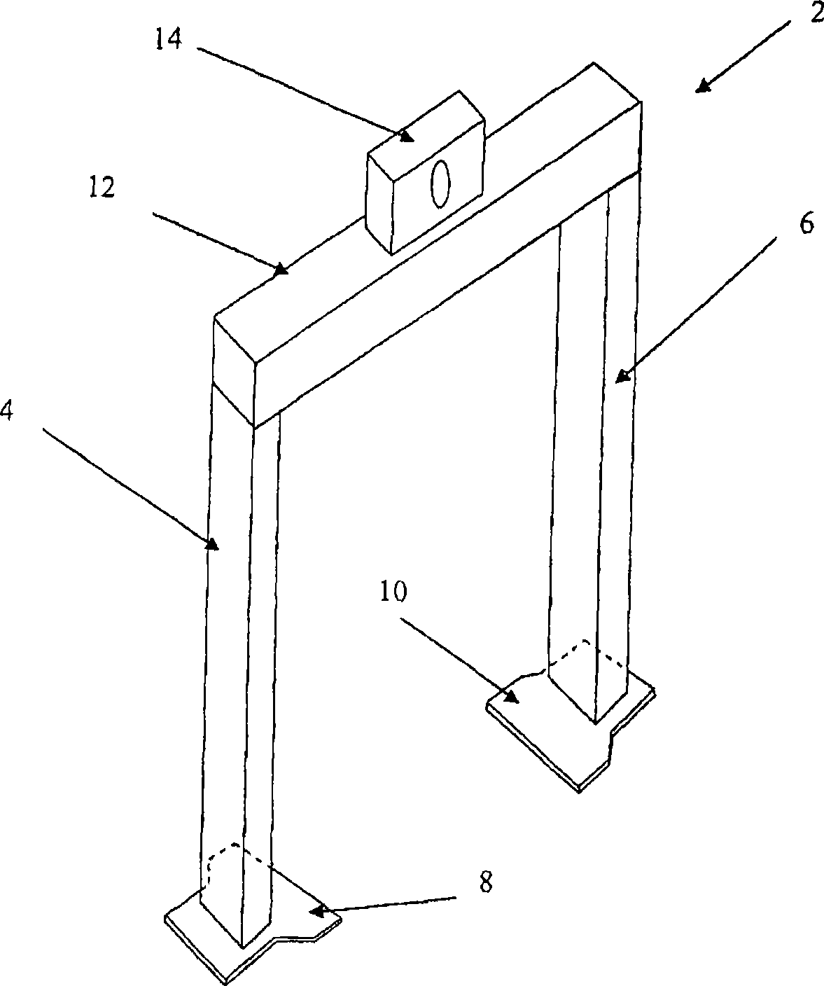
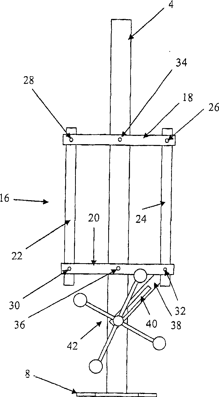
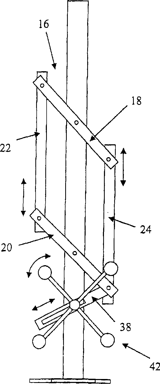
[0068] Stacks of coated glass panels are stacked on a stacking rack with the coated side facing the uprights of the stacking rack. The base of the stacking rack has a narrower width than the main faces of the stacks of glass panes, so that each stack of glass panes protrudes beyond the base of the stacking rack. Lift the stack of glass panels from the ground. adopted as Figure 12 A lifting frame of the type shown is used to rotate the stack of glass sheets 180 degrees about a vertical axis, ie to move the stack of glass sheets to another stacking rack so that the uncoated side of the glass sheets faces the uprights of the stacking rack.

[0069] The lifting frame employed has a first leg and a second leg. The first foot is connected to the bottom of the first leg and the second foot is connected to the bottom of the second leg. The tops of the two legs are connected by a cross member. A lifting chassis is attached to the cross member to allow movement of the lifting frame...


PUM


Abstract

Lifting frames (2) suitable for moving a pack of sheet material (244) are described. Lifting frames according to the invention comprise first and second legs (4, 5), each leg having a foot (8, 10) mounted thereon. The pack to be moved stands on the feet and is retained on the frame by pairs of fingers that can contact the front and rear faces of the pack. One pair of fingers (48, 50) can be raised whilst another pair of fingers retains the pack on the frame. This enables the pack of sheet material to be removed from either side of the frame (2), thereby reversing the orientation of the pack in a single lifting operation. Methods of moving a pack of sheet material using lifting frames according to the invention are also described.

Description

technical field [0001] The present invention relates to improvements in lifting frames, or to a lifting frame for transporting stacks of panels resting along one edge of the stack of panels and positioned substantially vertically; the invention also relates to the use of such A method for moving a stack of boards by a lifting frame. Background technique [0002] When flat glass is produced continuously, such as by a float process or a calendering process, a continuous glass ribbon is formed and annealed to relieve stress before being cut into glass sheets. The cut glass sheets are automatically stacked by a robot arm in a substantially vertical manner on an L-shaped holding frame called a stillage. Stacking racks consist of a lower support base and substantially vertical uprights against which panels are stacked. The support base and the uprights are usually perpendicular to each other, and the support base is usually inclined at an angle relative to the horizontal so that...

Claims


Application Information

Patent Timeline
Patent Type & Authority Applications(China)
IPC IPC(8): B65G49/06
CPCB65G49/061
Inventor N·J·伍德科克T·坎利夫
Owner PILKINGTON GROUP LTD
Learn More