Mechanism for connecting two flanged pipe ends or tube ends

A technology for tubes and hoses, which is applied in the field of devices at the free ends of tubes or hoses, and can solve problems such as damage to clamps, self-opening of clamps, damage to the function of tubes or hose connectors, etc.

Inactive Publication Date: 2009-07-22
卡尔·魏因霍尔德
View PDF1 Cites 2 Cited by
  • Summary
  • Abstract
  • Description
  • Claims
  • Application Information

AI Technical Summary

Problems solved by technology

[0004] Although known pipe or hose connectors have been used successfully for a long time, some applications may impair the function of the pipe or hose connector
If the spring stretches for any reason, this can cause the clamp to open on its own, and in some cases it can go out of control and damage the clamp

Method used


Image

  • Mechanism for connecting two flanged pipe ends or tube ends
  • Mechanism for connecting two flanged pipe ends or tube ends
  • Mechanism for connecting two flanged pipe ends or tube ends

Examples


Embodiment Construction

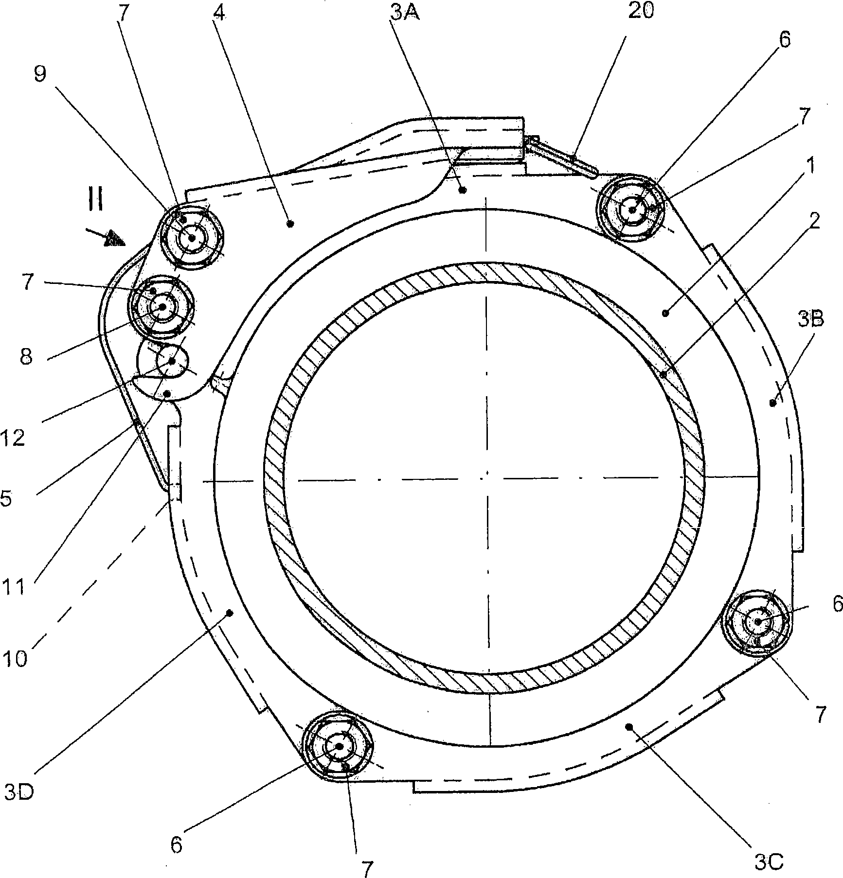
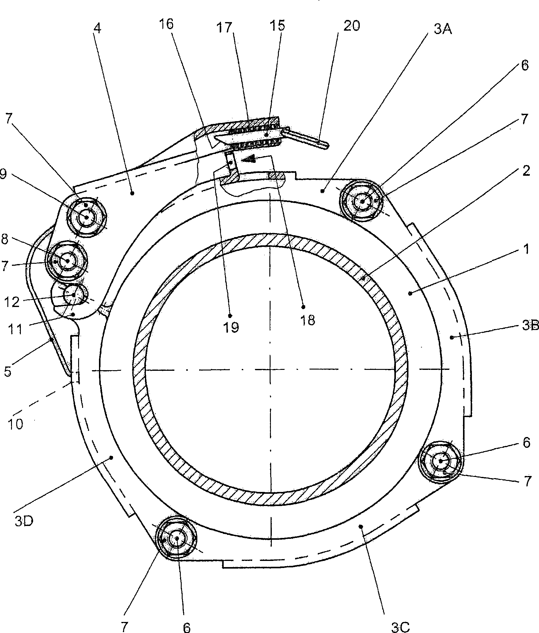
[0020] The connector shown in the drawings is a pipe connector for connecting two pipe ends 2 with flanges 1 . In the present exemplary embodiment, the device according to the invention consists of four mutually hinged clamp segments 3A, 3B, 3C, 3D and a locking mechanism consisting of a clamping lever 4 and a spring 5 .

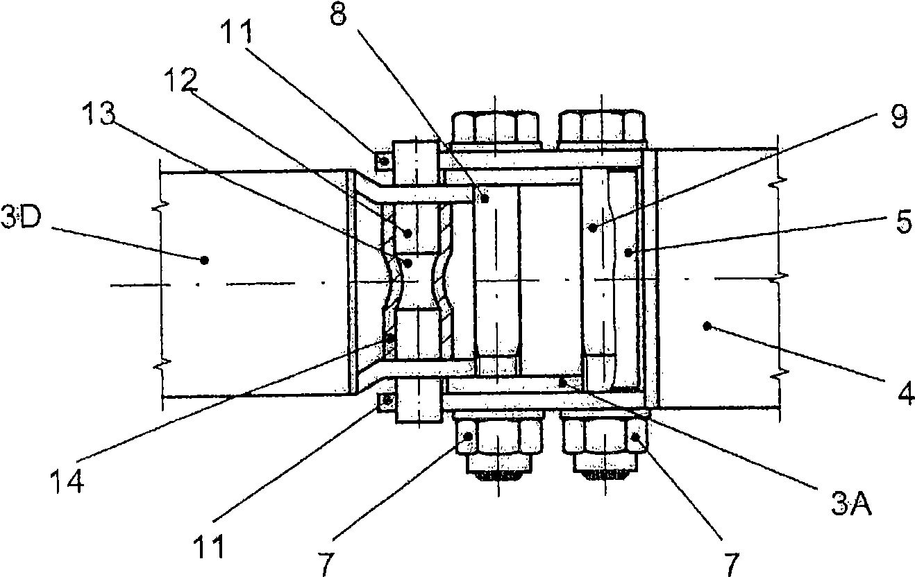
[0021] The clamp segments 3A, 3B, 3C, 3D are hinged to one another by means of hinge bolts 6 which are screwed at their ends with nuts 7 . The clamping lever 4 is fastened to the free end of the clamp section 3A by means of a further pivot bolt 8 , and the other pivot bolt 9 is used to fasten one end of the spring 5 . The other end of the spring 5 is hooked into a recess 10 at the free end of the (opposite) clamp section 3D. Also tighten the hinge bolts 8 and 9 with the nut 7 .

[0022] Of course, the connecting clip of the present invention can also be composed of other numbers of clip segments. In the simplest case (as in the prior art) there are only t...


PUM


Abstract

Disclosed is a mechanism for connecting free flanged pipe ends or tube ends (2, 22). Said mechanism comprises several hingedly interconnected clamp segments (3A, 3B, 3C, 3D) that have a substantially U-shaped cross-section, a clamping lever (4), one end of which is arranged at a free end of a clamp segment (3A), and at least one spring (5). The clamp segments (3A, 3B, 3C, 3D) externally overlap the flanges of the joined pipe ends or tube ends (2, 22) while the free ends of the first and the last clamp segment (3A and 3D) can be locked by means of the clamping lever (4) and the spring (5). In order to reliably prevent the closed mechanism from automatically opening under all circumstances, the clamping lever (4) can be positively connected to the free end of the adjacent clamp segment (3D)and can be locked in the tightened position.

Description

technical field [0001] The invention relates to a device for connecting free ends of flanged pipes or hoses, the device comprising: a plurality of mutually hinged clamp segments with a substantially U-shaped cross-section; a clamping rod, the clamp The tightening rod is arranged on the free end of a clamp section with the end side; and the spring, wherein the clamp section rests on the flanges of the pipe or hose ends that are pushed together, and the first and last The free end of a clamp section can be locked by means of a clamping lever and a spring. Background technique [0002] Various designs of such devices, referred to as pipe or hose connectors or pipe or hose clamps for short, have been known for a long time. The simplest arrangement of this type consists of a clamp with two clamp segments, which are hinged to each other at both ends by means of screws (EP 0 195 914 A2). For locking, the open clamp is placed on the flange of the pushed-together pipe ends or, corr...

Claims


Application Information

Patent Timeline
Patent Type & Authority Applications(China)
IPC IPC(8): F16L23/06
CPCF16L23/06
Inventor 卡尔·魏因霍尔德
Owner 卡尔·魏因霍尔德
Why Eureka
Try Eureka