Outer metering valve for fuel tank

A fuel tank and dosing valve technology, applied in fuel cells, fuel cell additives, gaseous engine fuels, etc., can solve the problems of product leakage, tool damage, shortening the service life of fuel tanks, etc., to simplify the joining process and prolong the use. longevity, the effect of eliminating errors

Inactive Publication Date: 2006-05-17
ILLINOIS TOOL WORKS INC
View PDF4 Cites 0 Cited by
  • Summary
  • Abstract
  • Description
  • Claims
  • Application Information

AI Technical Summary

Problems solved by technology

It reduces the life of the fuel tank due to product leakage not only from the internal seals in the tank, but also through the seals located in the valves
[0005] An important disadvantage of the second system, not only is there more leakage, but it is also complicated for the user
Also, attempting to fit the fuel tank with the shipping cap still in place can cause extensive damage to the tool

Method used


Image

  • Outer metering valve for fuel tank
  • Outer metering valve for fuel tank
  • Outer metering valve for fuel tank

Examples


Embodiment Construction

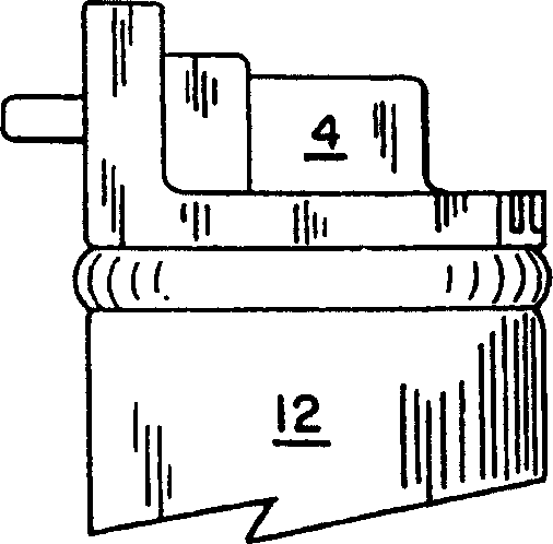
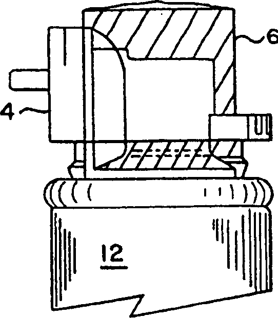
[0024] see now figure 1 and 2 , it can be seen that a prior art valve 4 is secured to the fuel tank 12 in a detached position by means of a securing cap or shipping cap 6 . As known in the prior art, such as figure 2 As shown, in order to move from the disengaged position to the engaged position, the user must first disassemble the retaining cap 6 together with the prior art valve 4 (these two parts are now connected together by a snap fit). The user then needs to disengage the retaining cap 6 from the prior art valve 4 and then place the prior art valve 4 on the fuel tank 12 to snap it into the engaged position. The engaged position is described in the prior art valve 4 engaged with the fuel tank 12. figure 1 can be seen in .

[0025] It is also known in the prior art that the fuel tank 12 is transported by fully engaging the prior art valve 4, as figure 1 shown. Because the prior art valve 4 is fully engaged with the fuel tank 12, the prior art valve is exposed to the...


PUM


Abstract

A valve constructed for use with a fuel tank in a disengaged position in which no fluid communication is established between the valve and the fuel tank and in an engaged position in which fluid communication is established between the valve and the fuel tank Liquid communication. The valve includes a valve body having a first member for maintaining a disengaged position, and a second member for maintaining an engaged position.

Description

technical field [0001] The present invention relates to improvements to an external metering valve for use with a fuel tank, liquefied gas tank or dispenser for dispensable fluids. Background technique [0002] As described in U.S. Patent Nos. 4,403,722, 4,483,474, 4,522,162 and 5,115,944 to Nikolich, all of which are incorporated by reference, it is known to dispense hydrocarbon fuels using a dispenser for dispensable liquids. Dispensed into a gas-powered tool, such as a gas-powered valve driver tool. Such valve actuation tools, as well as such fuel tanks, are commercially available from ITW-Paslode, a division of Illinois Tool Works, Inc., of Vernon Hills, Illinois, under the trademark IMPULSE. In particular, one suitable fuel tank is disclosed in the aforementioned Nikolich US Patent No. 5,115,944. [0003] Two systems are known for securing an external metering valve to such fuel tanks. In a first known system, the valve is fully engaged with the fue...

Claims


Application Information

Patent Timeline
Patent Type & Authority Patents(China)
IPC IPC(8): F16K27/00F17C13/04B25C1/08B65D83/44B05B9/04B25C1/04B65DB65D81/24B65D81/34B65D83/14B65D83/16B65D83/20B65D83/52B65D83/54B67B5/00F02B43/00H01M8/04
CPCB25C1/08B65D83/54H01M8/04082H01M8/04201Y02E60/50
Inventor 威廉E·理查森瓦莱里G·范斯坦莫哈梅德K·瓦格迪桑德拉J·威尔逊
Owner ILLINOIS TOOL WORKS INC
Why Eureka
Try Eureka