Stone-glass element with capillary cut

A capillary and glass technology, applied in the direction of glass/slag layered products, building materials, manufacturing tools, etc., can solve problems such as stone-glass composite material hazards

A capillary and glass technology, applied in the direction of glass/slag layered products, building materials, manufacturing tools, etc., can solve problems such as stone-glass composite material hazards

CN101501285AInactive Publication Date: 2009-08-05IISTONE

Image

  • Stone-glass element with capillary cut
  • Stone-glass element with capillary cut
  • Stone-glass element with capillary cut

Examples


Embodiment Construction

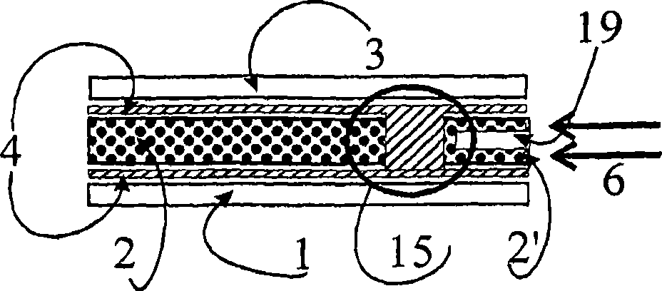
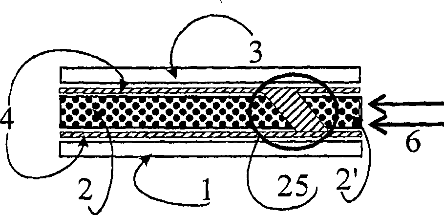
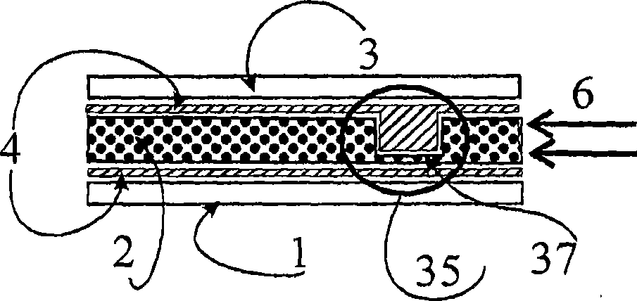
[0064] Figures 1 to 11 The cross-sectional views of each show the same principle structure of a stone-glass element with at least one stone plate 2 and a support plate 1 comprising at least one glass plate, which is passed through a A transparent or opaque cast resin layer 4 is attached over a large area to the stone slab 2 , wherein the surface of the stone slab 2 opposite the support slab 1 is provided with a moisture-proof layer or another cover 3 in the form of a plate. The areas drawn by circles or ellipses are shown respectively Figures 1 to 11 The design of different capillary cutouts. Moisture diffusion 6 acts on the cut surface shown exposed.

[0065] figure 1 A complete vertical capillary cut 15 is shown, which divides the stone. Here the cutout 19 shown horizontally for the remaining Figures 2 to 11 It is also representatively shown how the water uptake is further reduced in the edge strip formed by the capillary cutouts 15 and at the same time the drainage ...


PUM

PropertyMeasurementUnit
thicknessaaaaaaaaaa

Abstract

A stone-glass element having at least one stone plate (2) and one supporting plate (1) which comprises at least one glass pane which is connected over a large area to the stone plate by means of a transparent or opaque cast resin layer (4), wherein that surface of the stone plate situated opposite the supporting plate is provided with a moisture-repelling covering layer (7) or with a covering plate (3), is distinguished in that the stone plate has, parallel to at least one side edge, a capillary cut (15) which is completely filled with a sealant which prevents moisture diffusion (6) towards the interior of the stone plate (2). It is thus possible in a stone-glass element of the aforementioned type to use simple means to prevent moisture diffusion into the interior of the stone so as to avoid serious consequent damage. It is intended here to minimize any visual or aesthetic impairment of the element, and the technical outlay should not cause any significant increases in cost. A frameless facade construction should still continue to be possible.

Description

technical field [0001] The invention relates to a stone-glass element comprising at least one stone plate and a support plate comprising at least one glass plate which is connected over a large area to the The stone slabs are connected, wherein the surface of the stone slabs opposite the support plate is provided with a moisture-proof covering layer and / or a covering plate. Background technique [0002] Such a stone-glass element is known from EP 0 799 949 B1. In particular this document proposes a stone-glass element with a symmetrical glass / stone / glass structure. This element, especially in natural stone, has been produced since 1996 and can be used in both cold and warm areas. Here the stone slabs can be assembled from a variety of different stone slab elements. [0003] A special feature here is the nearly complete covering of the large-area stone slabs. But the cut edges of the elements are usually open and accessible to moisture, where the capillary action of the n...

Claims


Application Information

Patent Timeline
05 Aug 2009
Publication
CN101501285A
IPC
E04F13/14; E04C2/26; B23B9/04; B32B17/06
CPC
B32B17/06; E04F13/145; E04C2/26; B32B9/04; Y10T428/197; Y10T428/22; Y10T428/195; Y10T428/24182
Inventors
J·布兰克-博内; R·马夸特