Removable long-span thin car frame

A large-span, platform-based technology, which is used in stage installations, entertainment, installations for theaters and circuses, etc., can solve the problem of uneven load distribution, excessive wheel pressure, and difficulty in balancing the lateral horizontal additional load of the platform. and other problems, to achieve the effect of eliminating the horizontal additional load and reducing the wheel pressure

Inactive Publication Date: 2011-06-15
ENG DESIGN & RES INST OF GENERAL ARMAMENTS DEPT
View PDF0 Cites 0 Cited by
  • Summary
  • Abstract
  • Description
  • Claims
  • Application Information

AI Technical Summary

Problems solved by technology

[0003] Such a platform includes driving trolleys on both sides and a steel beam structure placed between the trolleys. A large-span steel beam structure is required to support the platform cover. The span and height of a conventional steel beam structure In a certain proportion, the larger the span, the higher the height should be correspondingly, so it forms a contradiction with the requirement of reducing the elevation of the above-mentioned platform as much as possible
[0004] In addition, for a large-span trolley, when it bears a heavy load, the steel beam structure will form a significant bending deformation with a low center and high ends, and a local bending moment will be generated at the connection between the two ends of the load-bearing steel beam structure and the driving trolley body , the load cannot be evenly distributed to all the supporting wheels of the driving trolley, which not only leads to excessive wheel pressure and accelerated wear of the single wheel during the operation of the trolley, but also causes the lateral horizontal additional force of the trolley under the heavy load and large deflection of the steel beam structure. The technical problem that the load is difficult to balance

Method used


Image

  • Removable long-span thin car frame
  • Removable long-span thin car frame
  • Removable long-span thin car frame

Examples


Embodiment Construction

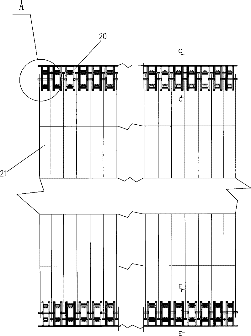
[0038] like figure 1 As shown, the mobile large-span thin platform vehicle platform of the present invention includes vehicle bodies 20 on both sides and a steel beam structure 21 arranged between the vehicle bodies 20 on both sides. Stressed steel beam structure (the following will be combined with the attached Figure 4-9 describe its structure in detail).

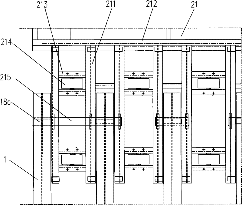
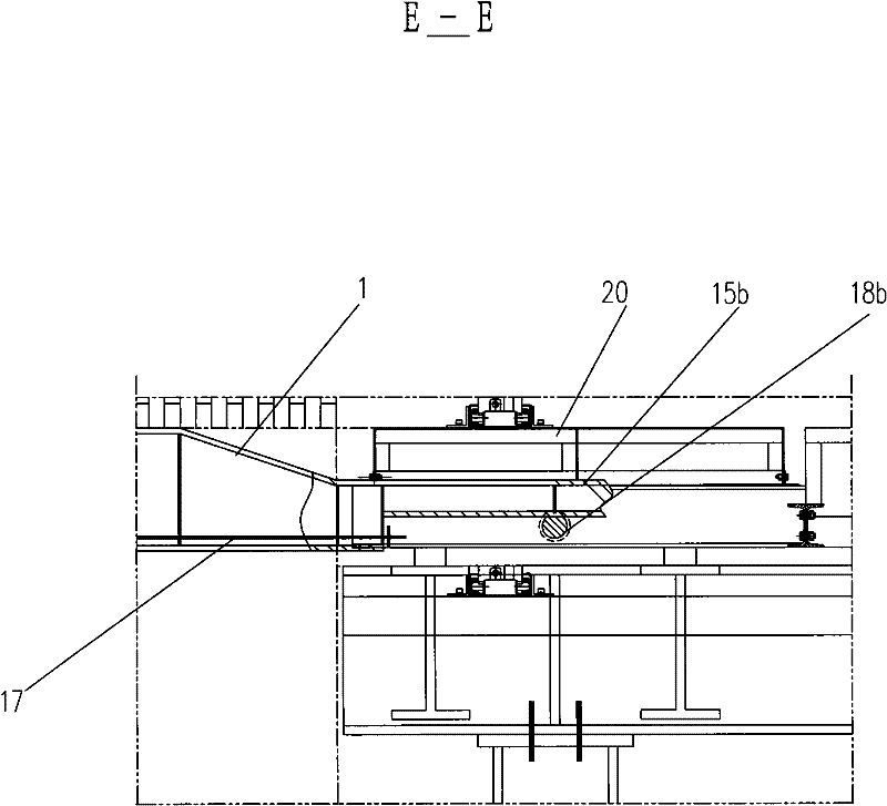
[0039] like figure 1 , 1a As shown, the steel beam structure 21 includes a plurality of main beams 1 extending in parallel, and the vehicle body 20 includes a plurality of parallel vehicle body beams 211, and each main beam 1 is arranged between pairs of vehicle body beams 211, and the paired A supporting frame 215 is arranged between the vehicle body beams 211, and the hinge shafts 18a, 18b are arranged in the supporting frame 215.

[0040] The outer end of the car body beam 211 of the car body 20 is provided with a side beam 212 perpendicular to the car body beam 211, and a supporting wheel frame 213 for placing a ...


PUM


Abstract

The invention provides a removable long-span thin car frame which is provided with removable car bodies (20) at both sides and a large span-height ratio external prestress steel girder structure, wherein the large span-height ratio external prestress steel girder structure is arranged between the car bodies at both sides; the steel girder structure (21) is arranged between a pair of car bodies (20) and comprises a plurality of main girders (1) arranged in parallel; one end of each main girder is fixedly connected with one of the car bodies, and the other end of each main girder is connected with the other car body in a floating way; and the position at the lower part of each main girder (1) is provided with a prestress stretching cable (17). When the main girders generate larger deformation by a heavy load, the car frame allows the main girders to generate proper horizontal displacement relative to the car bodies, thereby releasing great horizontal tensile force, greatly reducing wheel pressure and eliminating a horizontal additional load of the main girders on the car bodies at both sides of the car frame with the heavy load and large deflection.

Description

technical field [0001] The invention relates to a mobile platform, in particular to a large-span mobile platform capable of bearing heavy loads. Background technique [0002] In large-scale sports games or large-scale outdoor performances, in order to ensure that the audience in the front row of the stadium or performance venue can get a better viewing effect on the stage ground, the overall elevation of the stage used for the performance must be as low as possible, especially for installation on lifting platforms. Raising and receiving the underground car platform, limiting its own height plays a decisive role in reducing the overall elevation of the stage. [0003] Such a platform includes driving trolleys on both sides and a steel beam structure placed between the trolleys. A large-span steel beam structure is required to support the platform cover. The span and height of a conventional steel beam structure In a certain proportion, the larger the span is, the higher the ...

Claims


Application Information

Patent Timeline
Patent Type & Authority Patents(China)
IPC IPC(8): A63J1/00
Inventor 于建平陈威周凤广杨世才殷丽欣温庆林尚文郑辉李婷婷伊善真彭云涛
Owner ENG DESIGN & RES INST OF GENERAL ARMAMENTS DEPT
Why Eureka
Try Eureka